4-28
Group2- External terminal analog signal input function group
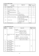
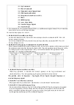
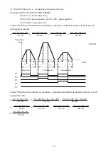
02-00 : AVI/ACI analog Input signal type select
=0 : AVI 0~10V, ACI 0~20mA
=1 : AVI 0~10V, ACI 4~20mA
=2 : AVI 2~10V, ACI 0~20mA
=3 : AVI 2~10V, ACI 4~20mA
02-01 : AVI signal verification Scan Time 1
~
100 (×4ms)
02-02 : AVI Gain(%) 0 ~ 1000
02-03 : AVI Bias(%) 0.0 ~ 100.0
02-04 : AVI Bias Selection 0 : positive 1 : Negative
02-05 : AVI Slope 0 : positive 1 : Negative
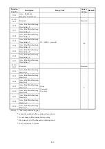
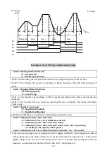
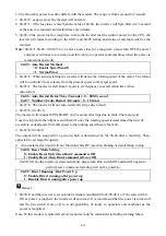
02-06 : ACI function Select
=0 : PID feedback signal =1 : ACI Bias signal input
1. 02-06=0 (PID feedback input)
When 02-06 is set 0 means the PID feedback input terminal is controlled by the setting of 09-00.
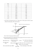
2. 02-06=1 (Bias Input)
ACI To regulate the Offset of the Keypad VR or AVI analog input, only the signal of 0~20
mAor4~20mA .
02-07 : ACI signal verification Scan Time 1~100 (× 4ms)
02-08 : ACI Gain(%)
0 ~ 1000
02-09 : ACI Bias(%)
0 .0~ 100.0
02-10 : ACI Bias Selection 0 : positive 1 : Negative
02-11 : ACI Slope 0 : positive 1 : Negative
Note : When 02-06 is set to 1, settings of 02-07
~
02-11 will not be effective.
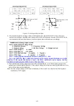
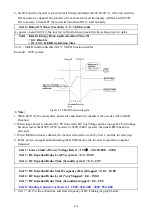
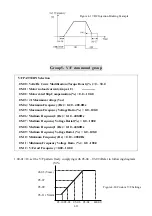
Example:
The setting of figure 4-18A: The setting of figure 4-18B:
2-02
/2-08
2-03
/2-09
2-04
/2-10
2-05
/2-11
2-09
2-02
/2-08
2-03
/2-09
2-04
/2-10
2-05
/2-11
2-09
A 100% 50% 0 0
100%
C 100% 50% 0 1
100%
B 100% 0% 0
0
100%
D
100% 0% 0 1
100%
0V
(0mA)
Upper Frequency
(00-07=60)
Hz
V
60Hz
30Hz
Bias
0Hz
0V
(0mA)
A
B
5V 10V
(20mA)
100%
50%
Upper Frequency Limit
(00-07=60)
Hz
V
60Hz
30Hz
0Hz
C
D
5V
10V
(20mA)
Bias
100%
50%
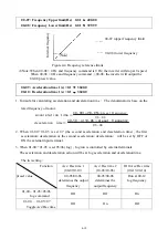
02-06=1function
V
10
0
Freq upper limit
00-07
Hz
AVI+ACI


