5-2
3.
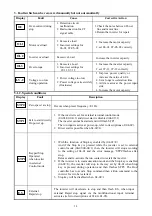
Faults which can be recovered manually but not automatically
Display Fault
Cause
Corrective
Action
Over-current during
stop
1. Detection circuit
malfunction
2. Bad connection for CT
signal cable
1.Check the noise between Power
line and motor line
2.Return the inverter for repair
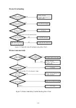
Motor overload
1. Excessive load
2. Incorrect settings for
06-01, 07-05~08
1. Increase the motor capacity
2. set 06-01, 07-05~08 correctly
Inverter overload
Excessive Load
Increase the inverter capacity
Over torque
1. Excessive Load
2. Incorrect settings for
07-11, 07-12
1. Increase the inverter capacity
2. set 07-11, 07-12 correctly
Voltage too low
during operation
1.
Power voltage too low
2. Power voltage varies widely
(fluctuates)
1.
Improve power quality or
increase the value of 4-04
2.
Set a longer acceleration time
3.
Add a reactor at the power input
side
4.
Increase the motor capacity
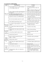
5.1.2. Special conditions
Display Fault
Description
Zero speed at stop
Occurs when preset frequency <0.1Hz
Fail to start directly
On power up.
1. If the inverter is set for external terminal control mode
(00-03/00-04=1) and direct start is disabled (04-09=1)
The inverter cannot be started and will flash STP1.
The run input is active at power-up, refer to descriptions of (04-09).
2. Direct start is possible when 04-09=0.
Keypad Stop
Operated
when inverter
in external
Control mode.
1. With the function of Stop key enabled by (04-02=0)
And if the Stop key is pressed while the inverter is set to external
control mode (00-03/00-04=1) then, the inverter will stop according
to the setting of 04-01 and the error message, ‘STP2’flashes after
stop.
Release and re-activate the run contact to restart the inverter.
2. If the inverter is in communication mode and the Stop key is enabled
(04-02=0), the inverter will stop in the way set by 04-01 when Stop
key is pressed during operation and then flashes STP2. The Host
controller has to send a Stop command then a Run command to the
inverter for it to be restarted.
3. Stop key will be disabled when 04-02=1
External
Rapid stop
The inverter will decelerate to stop and then flash E.S., when input
external Rapid stop signal via the multifunctional input terminal
activates (refer to descriptions of 01-00~01-05).
OL1
OL2
OL3
OC
LV-C
STP2
STP1
STP0
E.S.

