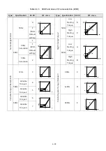
4-59
The function of Low Voltage Start:
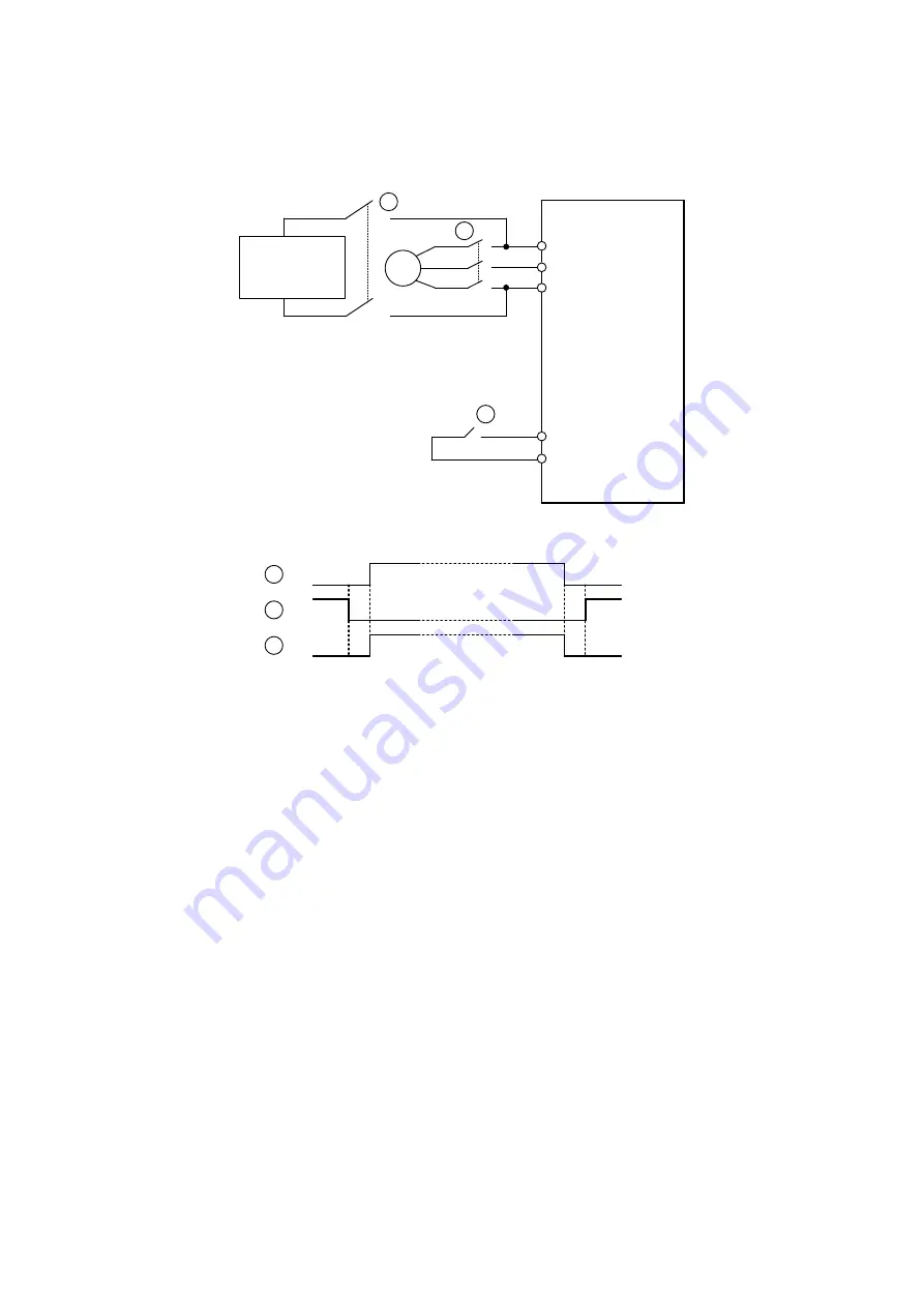
Wiring diagram:
R/L1
S/L2
T/L3
3
~
S1~S8
24VG
Inverter
Single phase
UPS or Battery
Specifications of single phase UPS and Battery
440V Class 207~380Vac, or 292~537Vdc
Input terminal of low voltage
start function
1
2
1
2
3
3
Timing chart of Electromagnetic contactor
Contactor 1 and 3 will b3 enable before the backup power is powered on, contactor 2 needs to keep opened.
Contactor 3 will be opened after contactor 1. Contactor 1 and 3 should keep closed before backup power was
removed and contactor 2 was be closed.
Notes of Low Voltage Start function:
1.
When low voltage start function is enabled (DI=62), cooling fan will not run, it can prevent the input voltage
be dropped.
2.
When low voltage start function is enabled, the function of input phase loss protection will be disabled.
3.
When low voltage start function is enabled, the output frequency of motor will be based on 07-31.
Summary of Contents for E510-201-SH
Page 1: ......
Page 28: ...3 14 b 200V 2HP 1 3PH 200V 3HP 20HP 400V 3HP 25HP IP20 NEMA1 ...
Page 29: ...3 15 c 200V 25HP 400V 30HP d 200V 30HP 40HP 400V 40HP 75HP ...
Page 51: ...3 37 3 5 Standard Wiring 10V AI1 AI2 AGND E P P ...
Page 72: ...4 6 4 1 4 Example of keypad operation Example 1 Modifying parameters ...
Page 74: ...4 8 4 1 5 Operation control ...
Page 206: ...4 140 Acceleration Deceleration calculation of mode 2 ...
Page 316: ...4 250 6 Timer mode 6 FLASH Timer mode 2 7 Timer mode 7 FLASH Timer mode 3 ...
Page 424: ...REVISIONS Date Manual Number Revision May 2017 4KA72X645T01 First edition ...
Page 425: ......


