4-64
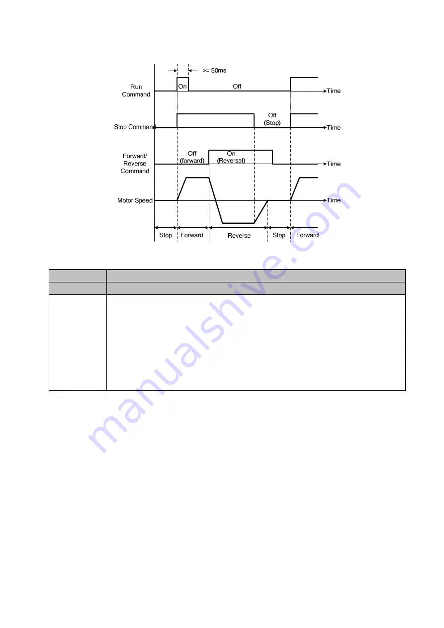
Terminal S1 must be closed for a minimum of 50ms to activate operation, please refer
below.
Figure 4.3.3 3-wire operation
00- 05
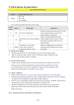
Main Frequency Command Source Selection
00- 06
Alternative Frequency Command Source Selection
Range
【0】:Up/Down of Keypad
【1】:Potentiometer on Keypad
【2】:External AI1 Analog Signal Input
【3】:External AI2 Analog Signal Input
【4】:External Up/Down Frequency Control
【5】:Communication Setting Frequency
【6】:Reserved
【7】:Pulse Input
(1)
00-05/00-06=0
Use the digital operator to enter frequency reference or to set parameter 05-01 (frequency
reference 1), please refer section 4.1.4 for the details.
If 00-06=0, the value of alternative frequency command only can be set in parameter 05-01.
(2)
00-05/00-06=1
Use the potentiometer to enter frequency source
(3)
00-05/00-06=2 or 3
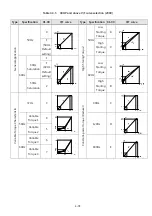
Use analog reference from analog input AI1 or AI2 to set the frequency reference (as shown in
Figure 4.4.4). Refer to parameters 04-00 to select the signal type
If the main frequency input signal is analog voltage signal, please set JP1 (AI1) to V. If the main
frequency input signal is analog current signal, please set JP1 (AI1) to I.
Summary of Contents for E510-201-SH
Page 1: ......
Page 28: ...3 14 b 200V 2HP 1 3PH 200V 3HP 20HP 400V 3HP 25HP IP20 NEMA1 ...
Page 29: ...3 15 c 200V 25HP 400V 30HP d 200V 30HP 40HP 400V 40HP 75HP ...
Page 51: ...3 37 3 5 Standard Wiring 10V AI1 AI2 AGND E P P ...
Page 72: ...4 6 4 1 4 Example of keypad operation Example 1 Modifying parameters ...
Page 74: ...4 8 4 1 5 Operation control ...
Page 206: ...4 140 Acceleration Deceleration calculation of mode 2 ...
Page 316: ...4 250 6 Timer mode 6 FLASH Timer mode 2 7 Timer mode 7 FLASH Timer mode 3 ...
Page 424: ...REVISIONS Date Manual Number Revision May 2017 4KA72X645T01 First edition ...
Page 425: ......


