4
-
180
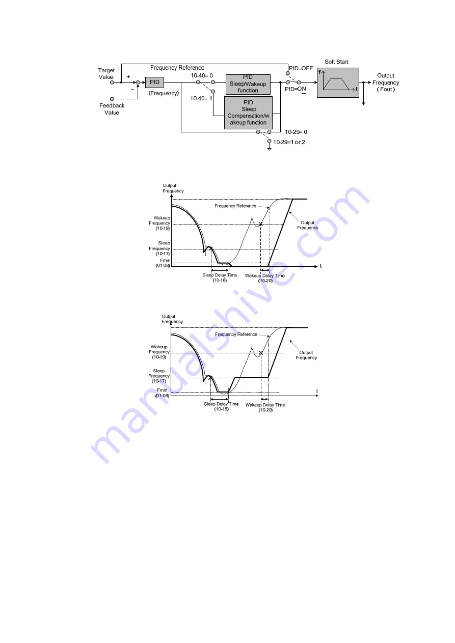
Refer to figure 4.3.83 (a), (b) and (c) for PID sleep/wakeup operation:
Figure 4.3.83 (a) PID control block diagram
Figure 4.3.83 (b) Timing diagram PID sleep / wakeup
Figure 4.3.83 (c) Timing diagram of PID sleep compensation/ wakeup
10-40=0, refer to Figure 4.3.83(b)
The PID sleep timer is enabled when the output frequency (Fout) falls below the PID sleep frequency
(10-17). When the sleep timer reaches the set PID sleep delay time (10-18) the inverter will
decelerate to a stop and enter the sleep mode.
10-40=1, refer to Figure 4.3.83(c)
When output frequency (Fout) is lower than PID sleep frequency set by 10-17, Timer of PID sleep
mode will run and the output frequency changes with the reference frequency (Fref) until it reaches
the minimum output frequency (Fmin) set by 01-08. When the PID sleep delay time (10-18) is
completed, the motor will run gradually to the PID sleep frequency set by 10-17.
Summary of Contents for E510-201-SH
Page 1: ......
Page 28: ...3 14 b 200V 2HP 1 3PH 200V 3HP 20HP 400V 3HP 25HP IP20 NEMA1 ...
Page 29: ...3 15 c 200V 25HP 400V 30HP d 200V 30HP 40HP 400V 40HP 75HP ...
Page 51: ...3 37 3 5 Standard Wiring 10V AI1 AI2 AGND E P P ...
Page 72: ...4 6 4 1 4 Example of keypad operation Example 1 Modifying parameters ...
Page 74: ...4 8 4 1 5 Operation control ...
Page 206: ...4 140 Acceleration Deceleration calculation of mode 2 ...
Page 316: ...4 250 6 Timer mode 6 FLASH Timer mode 2 7 Timer mode 7 FLASH Timer mode 3 ...
Page 424: ...REVISIONS Date Manual Number Revision May 2017 4KA72X645T01 First edition ...
Page 425: ......


