5-4
LED display
Description
Cause
Possible solutions
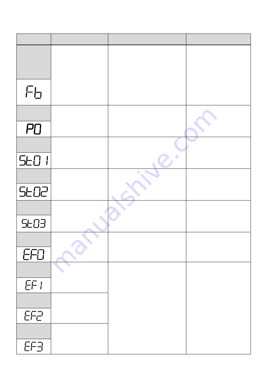
PID
Feedback
Loss
PID feedback signal falls
below level specified in
10-12 (PID feedback loss
detection level) for the
time specified in 10-13
(Feedback loss detection
time). Active when
parameter (10-11 = 2).
Feedback signal wire broken
Feedback sensor broken.
Check feedback wiring
Replace feedback sensor.
PO
Voltage Off
STO terminal 1 error
(Without STO/Filter model
only)
Terminal board Input SF1 and SG
are not connected
Check SF1 and SG connection
Safety 1
Error
STO terminal 1 error
(With STO/Filter model
only)
Terminal board Input SF1 and SG
are not connected
Check SF1 and SG connection
Safety 2
Error
STO terminal 2 error
(With STO/Filter model
only)
Terminal board Input SF2 and SG
are not connected
Check SF2 and SG connection
Safety 3
Error
STO terminal 3 error
Transformer voltage output of
inverter is not stable.
Replace the power board
Contact with TECO
External
fault 0
External fault (Modbus)
Modbus communication 0x2501 bit
2= "1"
Reset Modbus
communication 0x2501
bit 2= "1"
External
fault 1
External Fault
(Terminal S1)
External Fault Input Terminal
Check the fault reason
Reset external fault of
digital input
External
fault 2
External Fault
(Terminal S2)
External
fault 3
External Fault
(Terminal S3)
Summary of Contents for E510-201-SH
Page 1: ......
Page 28: ...3 14 b 200V 2HP 1 3PH 200V 3HP 20HP 400V 3HP 25HP IP20 NEMA1 ...
Page 29: ...3 15 c 200V 25HP 400V 30HP d 200V 30HP 40HP 400V 40HP 75HP ...
Page 51: ...3 37 3 5 Standard Wiring 10V AI1 AI2 AGND E P P ...
Page 72: ...4 6 4 1 4 Example of keypad operation Example 1 Modifying parameters ...
Page 74: ...4 8 4 1 5 Operation control ...
Page 206: ...4 140 Acceleration Deceleration calculation of mode 2 ...
Page 316: ...4 250 6 Timer mode 6 FLASH Timer mode 2 7 Timer mode 7 FLASH Timer mode 3 ...
Page 424: ...REVISIONS Date Manual Number Revision May 2017 4KA72X645T01 First edition ...
Page 425: ......


