5-15
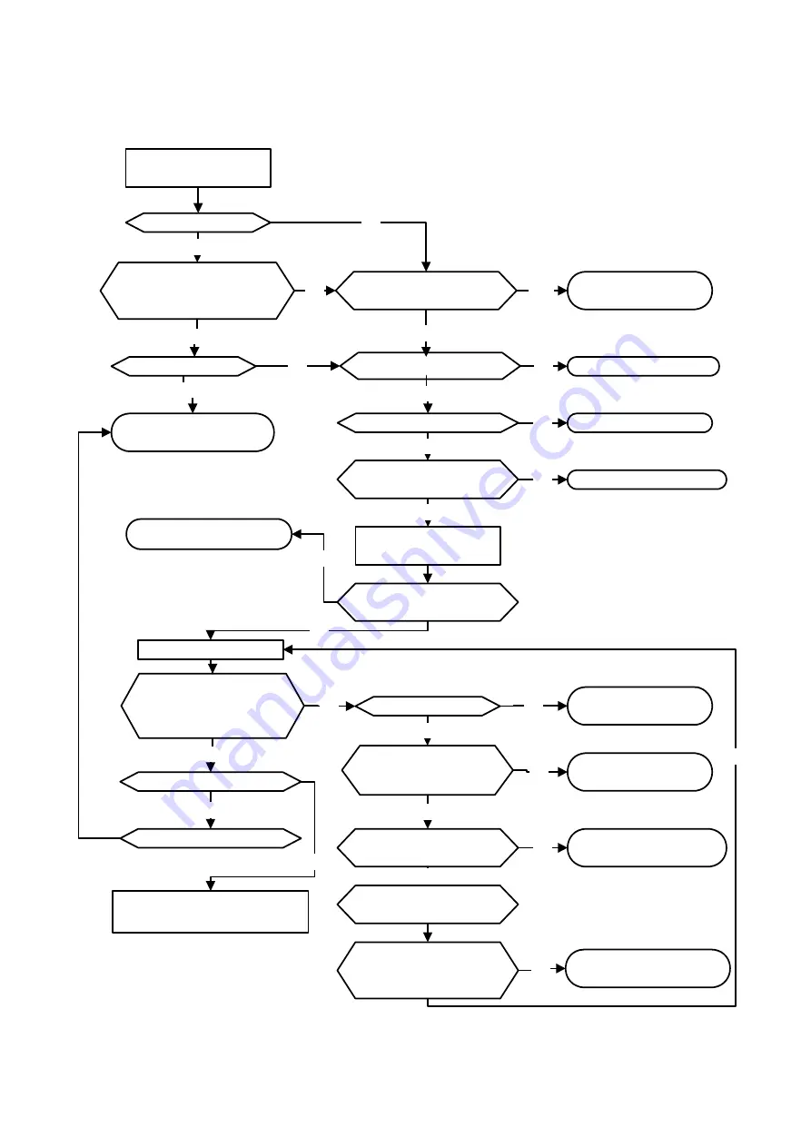
5.3 Troubleshooting of the Inverter
5.3.1 Quick troubleshooting of inverter
INV Fault
Visually check controller
and Drive boards
*to next page
Check burnt and
damaged parts
Consult with the supplier
Replace fuse
Consult with the supplier
Consult with the supplier
Check according to
displayed fault messages
Replace the pre-charge
resistor
Check terminals and
wiring
Consult with the supplier
Perform detailed check and
consult with the supplier
Is fault known?
Symptoms other than burn
out, damage, or fuse
meltdown in the inverter?
Any Symptoms of burn
out and damage?
Is the main circuit DM
intact?
Fault signal?
Is the fuse intact
?
Is the main circuit
I.G.B.T intact?
Any visual
abnormalities?
Are displays and
indicators of the
operating unit working
normally?
Is +5V control voltage
correct?
Is the DC input voltage
controlling the power
correct
Any fault display?
What the message
?
Is LED lit?
Replace control board
and digital operating unit
Is the error eliminated
after replacing control
board?
YES
NO
NO
YES
NO
NO
NO
YES
YES
YES
YES
NO
NO
NO
YES
YES
YES
YES
NO
NO
YES
NO
YES
NO
YES
NO
YES
NO
Apply the power
Summary of Contents for E510-201-SH
Page 1: ......
Page 28: ...3 14 b 200V 2HP 1 3PH 200V 3HP 20HP 400V 3HP 25HP IP20 NEMA1 ...
Page 29: ...3 15 c 200V 25HP 400V 30HP d 200V 30HP 40HP 400V 40HP 75HP ...
Page 51: ...3 37 3 5 Standard Wiring 10V AI1 AI2 AGND E P P ...
Page 72: ...4 6 4 1 4 Example of keypad operation Example 1 Modifying parameters ...
Page 74: ...4 8 4 1 5 Operation control ...
Page 206: ...4 140 Acceleration Deceleration calculation of mode 2 ...
Page 316: ...4 250 6 Timer mode 6 FLASH Timer mode 2 7 Timer mode 7 FLASH Timer mode 3 ...
Page 424: ...REVISIONS Date Manual Number Revision May 2017 4KA72X645T01 First edition ...
Page 425: ......


