4- 84
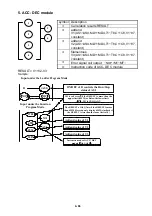
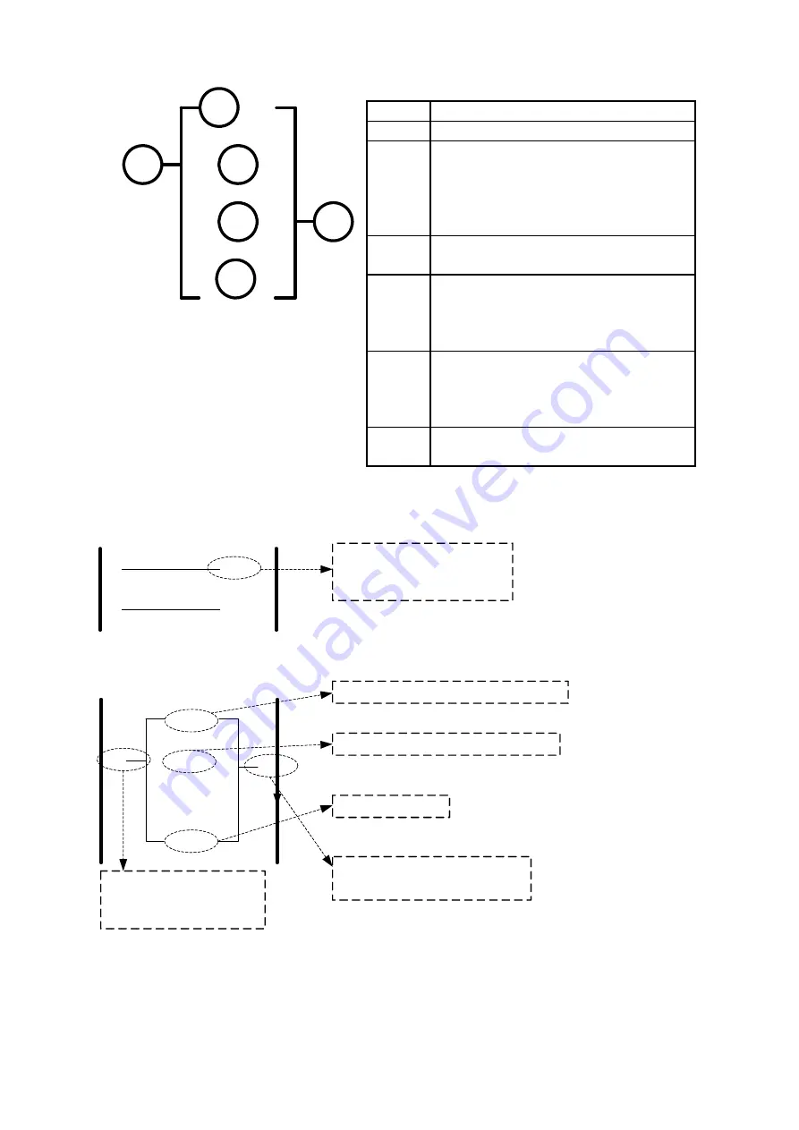
3. Analog comparator
Symbol Description
c
Analog comparison mode (1-3)
d
Selection of the input comparison
value
(AS1~AS4,MD1~MD4,T1~T8,C1~C8,V
1~V7)
e
Setting reference comparison value
(up limit)
f
Setting reference comparison value
(
Upper Limit
)
(AS1~AS4,MD1~MD4,T1~T8,C1~C8,V
1~V7,count)
g
Setting reference comparison value
(
Lower Limit
)
(AS1~AS4,MD1~MD4,T1~T8,C1~C8,V
1~V7,count)
h
Output terminals of analog
comparator
(G1~G4)
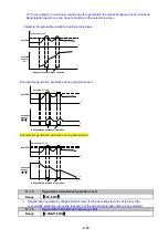
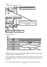
Analog Comparison Mode (1-3)
(1)
Analog comparator mode 1
(
e
≤
g
,
h
ON)
(G1)
(
T1
)
The target value of G1 is
determined by the
present value of T1
1
4.0
G1
T1
Input under the Function Program Mode
Input under the Ladder Program Mode
0.3
Because present input
Value(0.3)<lower
limit(4.0),so G1is ON
Analog comparision mode is model
Lower limit is 4.0
The present value of Timer 1 is 0.3
The number of Analog
comparision:G1~G8
(2)
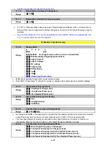
Analog comparator mode 2
(
e
≥
f
,
h
ON)
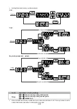
(3)
Analog comparator mode 3
(
g
≤
e
≤
f
,
h
ON)
1
3
4
2
6
5
Summary of Contents for e510 series
Page 1: ......
Page 8: ...2 1 Chapter 2 Part Number Definition 2 1 Model Part Number...
Page 13: ...3 4 Screw M4 Screw M4...
Page 34: ...3 25 c Three phase 200V 8 10HP 400V 8 15HP E510 Frame 3 E510 Frame 3 NEMA1...
Page 35: ...3 26 d Three phase 200V 15 20HP 400V 20 25HP E510 Frame 4 E510 Frame 4 NEMA1...
Page 43: ...3 34 3 5 2 Single Three phase Model 200V E510 2P5 H E510 201 H E510 202 H E510 203 H...
Page 197: ......

