App3-3
2.2 CRC CHECK
:CRC Check Code is calculated from SLAVE Address to end of the data.
The
calculation method is illustrated as follow:
(1). Load a 16-bit register with FFFF hex (all’s1).Call this the CRC register.
(2). Exclusive OR the first 8-bit byte of the message with the low-order byte of the 16-bit
CRC register, putting the result in the CRC register.
(3). Shift the CRC register one bit to the right (toward the LSB), Zero-filling the MSB,
Extract and examines the LSB.
(4). (If the LSB was 0): Repeat Steps(3)(another shift). (If the LSB was 1): Exclusive OR
the CRC register with the polynomial value A001 hex (1010 0000 0000 0001), putting the
result in the CRC register.
(5). Repeat Steps (3) and (4) until 8 shifts been performed. When this is done, a
complete 8-bit byteWill be processed .
(6). Repeat Steps (2) through (5) for next 8-bit byte of the message, Continue doing this
until all bytes have been processed. The final content of the CRC register is the CRC
value. Placing the CRC into the message: When the 16-bit CRC (2 8-bit bytes) is
transmitted in the message, the Low-order byte will be transmitted first, followed by the
high-order byte, For example, if the CRC value is 1241 hex, the CRC-16 Upper put the
41h, the CRC-16 Lower put the 12h.
z
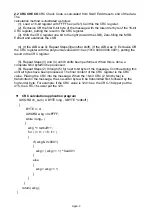
CRC calculation application program
UWORD ch_sum ( UBYTE long , UBYTE *rxdbuff )
{
BYTE i = 0;
UWORD wkg = 0xFFFF;
while ( long-- )
{
wkg ^= +;
for ( i = 0 ; i < 8; i++ )
{
if ( wkg & 0x0001 )
{
wkg = ( wkg >> 1 ) ^ 0xa001;
}
else
{
wkg = wkg >> 1;
}
}
}
return( wkg );
}
Summary of Contents for e510 series
Page 1: ......
Page 8: ...2 1 Chapter 2 Part Number Definition 2 1 Model Part Number...
Page 13: ...3 4 Screw M4 Screw M4...
Page 34: ...3 25 c Three phase 200V 8 10HP 400V 8 15HP E510 Frame 3 E510 Frame 3 NEMA1...
Page 35: ...3 26 d Three phase 200V 15 20HP 400V 20 25HP E510 Frame 4 E510 Frame 4 NEMA1...
Page 43: ...3 34 3 5 2 Single Three phase Model 200V E510 2P5 H E510 201 H E510 202 H E510 203 H...
Page 197: ......


