I
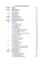
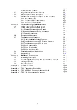
E510 Table of Contents
Chapter 0
Preface
0-1
0.1 Preface
0-1
Chapter 1
Safety Precautions
1-1
1.1
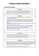
Before Power UP
1-1
1.2
During Power UP
1-2
1.3 Before
Operation
1-2
1.4 During
Operation
1-2
1.5 Inverter
Disposal
1-3
Chapter 2
Part Number Definition
2-1
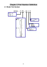
2.1
Model Part Number
2-1
2.2
Standard Product Specification
2-2
Chapter 3
Environment & Installation
3-1
3.1 Environment
3-1
3.2
Installation
3-2
3.2.1
Installation method
3-2
3.2.2 Installation space
3-15
3.2.3
De-rating curve
3-
17
3.3 Wiring
guidelines
3-17
3.3.1 Power Cables
3-17
3.3.2 Control Cable selection and Wiring
3-18
3.3.3 Wiring and EMC guidelines
3-19
3.3.4
Failure liability
3-
20
3.3.5 Considerations for peripheral equipment
3-
21
3.3.6 Ground connection
3-
22
3.3.7 Inverter exterior
3-
23
3.4 Specifications
3-
29
3.4.1 Product Specifications
3-
29
3.4.2 General Specifications
3-
31
3.5 Standard
wiring
3-
33
3.5.1 Single phase
3-
33
3.5.2 Single/ Three phase
3-
34
3.5.3 Three phase
3-
35
3.6 Terminal
Description
3-
36
3.6.1 Description of main circuit terminals
3-
36
3.6.2 Control circuit terminal description
3-
38
3.7 Outline
Dimensions
3-
40
3.8 EMC
filter
disconnection
3-
49
Chapter 4
Software Index
4-1
4.1
Keypad Description
4-1
4.1.1 Operator Panel Function
4-1
4.1.2 Digital display Description
4-2
4.1.3 Digital display setup
4-4
4.1.4 Keypad Operation Example
4-5
Summary of Contents for e510 series
Page 1: ......
Page 8: ...2 1 Chapter 2 Part Number Definition 2 1 Model Part Number...
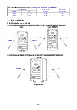
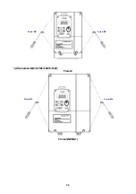
Page 13: ...3 4 Screw M4 Screw M4...
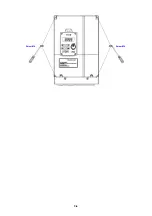
Page 34: ...3 25 c Three phase 200V 8 10HP 400V 8 15HP E510 Frame 3 E510 Frame 3 NEMA1...
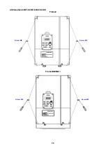
Page 35: ...3 26 d Three phase 200V 15 20HP 400V 20 25HP E510 Frame 4 E510 Frame 4 NEMA1...
Page 43: ...3 34 3 5 2 Single Three phase Model 200V E510 2P5 H E510 201 H E510 202 H E510 203 H...
Page 197: ......


