II
4.1.5 Operation Control
4-7
4.2
Programmable Parameter Groups
4-8
4.3 Parameter
Function
Description
4-
27
4.4 Specification
Description on Built-in PLC Function
4-77
4.4.1 Basic Instruction
4-77
4.4.2 Function of Basic Instruction
4-78
4.4.3 Application Instructions
4-79
Chapter 5
Troubleshooting and Maintenance
5-1
5.1
Error Display and Corrective Action
5-1
5.1.1 Manual Reset and Auto-Reset
5-1
5.1.2 Keypad Operation Error Instruction
5-3
5.1.3 Special conditions
5-4
5.2 General
troubleshooting
5-5
5.3
Troubleshooting of Inverter
5-6
5.3.1 Quick troubleshooting of Inverter
5-6
5.3.2 Troubleshooting for OC, OL error displays
5-8
5.3.3 Troubleshooting for OV, LV error
5-9
5.3.4 Motor not running
5-10
5.3.5 Motor Overheating
5-11
5.3.6 Motor runs unevenly
5-
12
5.4
Routine and periodic inspection
5-12
5.5 Maintenance
5-
14
Chapter 6
Peripheral Components
6-1
6.1 Reactor
Specifications
6-1
6.2
Electromagnetic Contactor and No fuse circuit breaker
6-1
6.3 Fuse
Specification
6-2
6.4 Brake
Resistance
6-2
Appendix 1
Instructions for UL
App1-1
Appendix 2
E510 Parameters Setting List
App2-1
Appendix 3
E510 MODBUS Communication protocol
App3-1
Appendix 4
E510 PLC Communication protocol
App4-1
Summary of Contents for e510 series
Page 1: ......
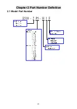
Page 8: ...2 1 Chapter 2 Part Number Definition 2 1 Model Part Number...
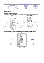
Page 13: ...3 4 Screw M4 Screw M4...
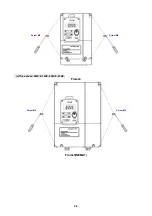
Page 34: ...3 25 c Three phase 200V 8 10HP 400V 8 15HP E510 Frame 3 E510 Frame 3 NEMA1...
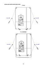
Page 35: ...3 26 d Three phase 200V 15 20HP 400V 20 25HP E510 Frame 4 E510 Frame 4 NEMA1...
Page 43: ...3 34 3 5 2 Single Three phase Model 200V E510 2P5 H E510 201 H E510 202 H E510 203 H...
Page 197: ......


