3-35
3.5.3 Three phase
Frequency indicator device
or PID input
Frequency
Indicator
(
MCCB
L1(L)
+
T1
L3(N)
(
10V
AI1
AI2
MC
AGND
0 ~10V
M
0~20mA
-
L2
(
Inverter
output
AC
Power
source
Induction
Motor
S3
S4
S5
S6
S2
FWD (Run/Stop)
S1
R2C
RS485
CON2
AO
AGND
+
-
0~10VDC
NPN
PNP
AI1 AI2
AV1AV2
J
P
1
Ground
Three phases power input
REV (Run/Stop)
R2A
R1A
R1B
R1C
T2
T3
J
P
2
J
P
3
Safety Function Input
SG
SF
Speed Control
M
u
ltifu
n
ction
Inpu
t Term
inals
E
E
E
P
P
Reset
*
*3
1:Data+
2:Data-
3:Data+
4:Reserved
5:Reserved
6:Data-
7:5V
8:GND
+ 24V(PNP)
COM (NPN)
*4
Indicates twisted-pair shield wire
P
Shows control circuit
Shows main circuit
Indicates shield wire
*1: Independent protection circuit is suggested to be installed for the purpose of protecting the circuit.
*2: If the jumper wire between SF and SG is connected, the inverter stops output.
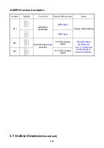
*3: JP1:NPN/PNP selection, JP2:AI1 0~10V/0~20mA selection, JP3:AI2 0~10V/0~20mA selection
*4: Connect to terminal Com or +24vdc depending on position of JP1.
Model:
200V:E510-205-H3/E510-208-H3/E510-210-H3/
E510-215-H3/E510-220-H3
400V:E510-401-H3(F)/ E510-402-H3(F)/ E510-403-H3(F)/
E510-405-H3(F)/E510-408-H3(F)/E510-410-H3(F)/
E510-415-H3(F)/E510-420-H3(F)/E510-425-H3(F)
Summary of Contents for e510 series
Page 1: ......
Page 8: ...2 1 Chapter 2 Part Number Definition 2 1 Model Part Number...
Page 13: ...3 4 Screw M4 Screw M4...
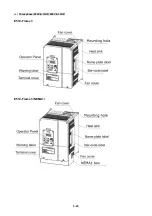
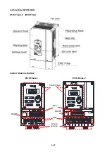
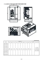
Page 34: ...3 25 c Three phase 200V 8 10HP 400V 8 15HP E510 Frame 3 E510 Frame 3 NEMA1...
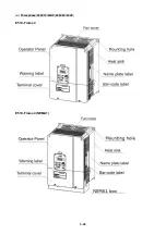
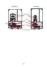
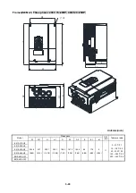
Page 35: ...3 26 d Three phase 200V 15 20HP 400V 20 25HP E510 Frame 4 E510 Frame 4 NEMA1...
Page 43: ...3 34 3 5 2 Single Three phase Model 200V E510 2P5 H E510 201 H E510 202 H E510 203 H...
Page 197: ......

