3-36
3.6 Terminal Description
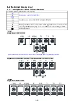
3.6.1 Description of main circuit terminals
Terminal symbols
TM1 Function Description
L1(L)
L2
L3(N)
Main power input, L1(L)/L2/L3(N)
T1
T2
T3
Inverter output, connect to U/V/W terminals of motor
P
BR
Braking resistor connection terminal: Used in applications when it is required to
stop a high inertia load rapidly. (refer to specifications of the braking resistor)
Ground terminal
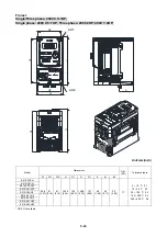
Frame1
Single phase: 200V 0.5~1HP
Note: the screw on L2 terminal is removed for the single phase input supply models.
Single/Three phase:200V 0.5~1HP; Three phase:200V 2HP; 400V 1~2HP;
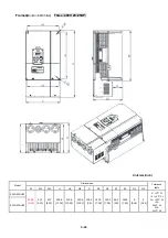
Frame2
Single phase:200V 2~3HP;
L1(L) L2 L3(N) P BR
T1 T2 T3
L1(L) L2 L3(N)
T1 T2 T3
P
BR
L1(L) L2 L3(N)
T1 T2 T3
P
BR
Summary of Contents for e510 series
Page 1: ......
Page 8: ...2 1 Chapter 2 Part Number Definition 2 1 Model Part Number...
Page 13: ...3 4 Screw M4 Screw M4...
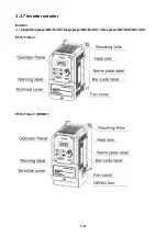
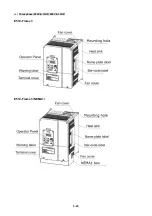
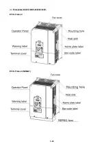
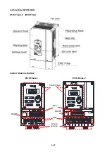
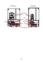
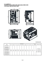
Page 34: ...3 25 c Three phase 200V 8 10HP 400V 8 15HP E510 Frame 3 E510 Frame 3 NEMA1...
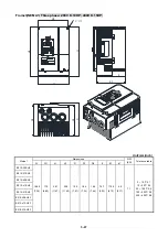
Page 35: ...3 26 d Three phase 200V 15 20HP 400V 20 25HP E510 Frame 4 E510 Frame 4 NEMA1...
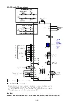
Page 43: ...3 34 3 5 2 Single Three phase Model 200V E510 2P5 H E510 201 H E510 202 H E510 203 H...
Page 197: ......


