4-34
¾
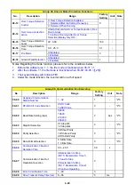
In vector mode, selected by parameter 00-00=
【
1
】
, set the motor name plate data in parameters
02-01
、
02-03
~
02-06 then activate the out auto tune function by setting parameter 02-14 = 1..
¾
Auto tune function will set the inverter to run with the specific motor connected to obtain the best
motor performance.
¾
During the Auto tune. “AT” will be displayed on the inverter and there will be an automatic motor
parameter mearurments which will be stored in parameters 02-15
~
02-16.
¾
After successful auto tune function the display will show “End” and the display will return to command
frequency display. Parameter 02-14 will reset to 0.
¾
Auto tune function must be carried out again if the motor is replaced..
03- External Digital Inputs and
Relay
Output Functions
03- 00
Multifunction Input Term. S1
03- 01
Multifunction Input Term. S2
03- 02
Multifunction Input Term. S3
03- 03
Multifunction Input Term. S4
03- 04
Multifunction Input Term. S5
03- 05
Multifunction Input Term. S6
Range
【
0
】
:Forward/Stop Command
----------------
(
Parameters
00- 02/00-03=1
&
00-04)
【
1
】
:Reverse/Stop Command
----------------
(
Parameters
00- 02/00-03=1
&
00-04)
【
2
】
:Preset Speed 0
---------------------------( Parameter
(5- 02))
【
3
】
:Preset Speed 1
------------------------ -----
(
Parameter
(5-03))
【
4
】
:Preset Speed 2
------------------------ -----
(
Parameter
(5-05))
【
5
】
:Preset Speed 3
------------------------ -----
(
Parameter
(5-09))
【
6
】
:JOG Forward Command
------------
(
Parameters
00-18~00-20)
【
7
】
:JOG Reverse Command
------------
(
Parameters
00-18~00-20)
【
8
】
:Up
Command
---------
(
Parameters
00- 05/00- 06=4
&
03-06/03-07)
【
9
】
:Down
Command
-----
(
Parameters
00- 05/00- 06=4
&
03-06/03-07)
【
10
】
: 2
nd
Acc/Dec Times
【
11
】
: Disable Acc/Dec
【
12
】
: Main/ Alternative Run Source Selec
t----
(
Parameters
00- 02/00- 03)
【
13
】
: Main/ Alternative Frequency Command Select
----
(
Parameters
00- 05/00- 06)
【
14
】
: Rapid Stop (controlled deceleration stop)
【
15
】
: Base Block (Coast to stop)
【
16
】
: Disable PID Function
----------
(
Parameter
Goup10)
【
17
】
: Reset
【
18
】
: Enable Auto Run Mode
-----------
(
Parameter
Goup6)
【
19
】
: Speed Search
【
20
】
: Energy Saving(V/F)
【
21
】
: Reset PID integral value to Zero
【
22
】
: Pulse Input
【
23
】
: Pulse input Counter Reset
【
24
】
: PLC Input
【
25
】
:
Reserved
【
26
】
:
Reserved
【
27
】
: Enable KEB Function
【
28
】
:
Fire mode function (Valid for software issued after rev. 1.1 )
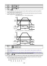
Set up examples and descriptions for Parameters 03-00 to 03-05 are noted in the following pages
sections 1 to 13.
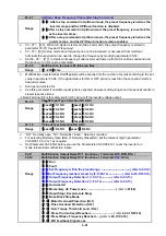
1. For setting parameters 03- 00~03- 05 to
【
0
,
1
】
External Run/Stop Control, refer to 00- 04.
1A) 2-wire method. Mode 1.
Example: FWD/STOP and REV/STOP from two inputs ( S1&S2)
Set 00- 04=
【
0
】
; S1:03- 00=
【
0
】
(
FWD/STOP
); S2:03- 01=
【
1
】
(
REV/STOP
);
Summary of Contents for e510 series
Page 1: ......
Page 8: ...2 1 Chapter 2 Part Number Definition 2 1 Model Part Number...
Page 13: ...3 4 Screw M4 Screw M4...
Page 34: ...3 25 c Three phase 200V 8 10HP 400V 8 15HP E510 Frame 3 E510 Frame 3 NEMA1...
Page 35: ...3 26 d Three phase 200V 15 20HP 400V 20 25HP E510 Frame 4 E510 Frame 4 NEMA1...
Page 43: ...3 34 3 5 2 Single Three phase Model 200V E510 2P5 H E510 201 H E510 202 H E510 203 H...
Page 197: ......

