4-37
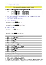
3. 03- 00~03- 05=
【
6, 7
】
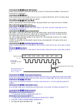
Forward/ Reverse JOG
When an input terminal is set to function
【
6
】
and is turned on, inverter will work in jog forward mode.
When an input terminal is set to function
【
7
】
and is turned on, inverter will work in jog reverse mode.
Note: If jog forward and jog reverse function is enabled at the same time, inverter will enter stop mode.
4. 03- 00~03- 05=
【
8, 9
】
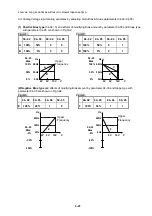
UP/DOWN
When an input terminal is set to function
【
8
】
and turned on ,frequency command will increased according
to the UP/DOWN and increment/decrement step set in parameter 03-06.
If the input is kept on continuously, the frequency command increases accordingly until the upper
frequency limit is reached.
When an input terminal is set to function
【
9
】
and is turned on , frequency command decreases according
to the UP/DOWN increment/decrement step set in parameter 03-06.
If the input is kept on continuously, the frequency command decreases accordingly and in relation to
settings for parameter 03-06 and 3-07 until Zero speed is reached.
Refer to group 3 parameter description.
Note:
※
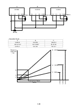
The UP/DOWN target frequency is determined by the time that the signal is kept on, including
the acceleration /deceleration time.
5. 03- 00~03- 05=
【
10
】
2
nd
Acc/Dec time
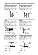
When an input terminal is set to function
【
10
】
and is turned on ,the actual acceleration and deceleration
time will be according to the time for 2
nd
Accel/Decel set in parameters 00-16 and 00-17.
if the input is turned off, the acceleration and deceleration times will be according to the default accel/decal
1 set in parameters 00-14 & 00-15.
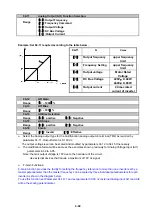
Example:
00-12
(
Frequency upper limit
)
=50HZ(Defaults)
03-00
(
Termina S1
)
= 8
03-06
(
up/down frequency
step
)
=0
00-14
(
accelerating time 1
)
=5S
00-16 (accelerating time 2) =10S(Defaults)
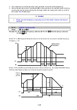
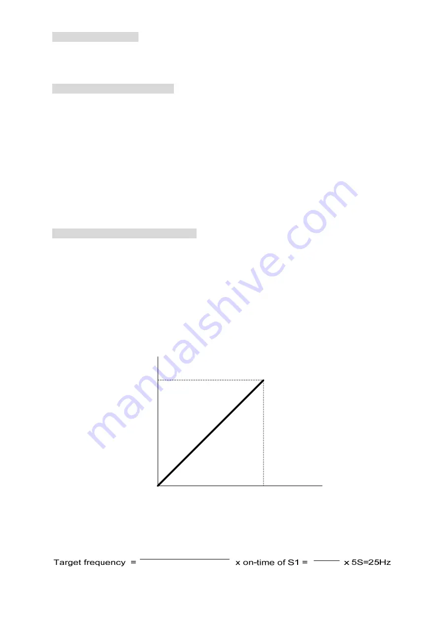
When s1 is ON for 5 s, the actual accelerating time of inverter will be 2.5s.
Explain:
50Hz
(
Frequency
upper limit
)
0
10s(accelerating
time 2)
Hz
T
Diagram a
Diagram a: Target frequency is determined by the Frequency upper limit, the on-time and accelerating
time 2..
upper frequncy
acceleranting time2
10S
50Hz
Summary of Contents for e510 series
Page 1: ......
Page 8: ...2 1 Chapter 2 Part Number Definition 2 1 Model Part Number...
Page 13: ...3 4 Screw M4 Screw M4...
Page 34: ...3 25 c Three phase 200V 8 10HP 400V 8 15HP E510 Frame 3 E510 Frame 3 NEMA1...
Page 35: ...3 26 d Three phase 200V 15 20HP 400V 20 25HP E510 Frame 4 E510 Frame 4 NEMA1...
Page 43: ...3 34 3 5 2 Single Three phase Model 200V E510 2P5 H E510 201 H E510 202 H E510 203 H...
Page 197: ......


