4-39
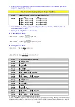
11. 03- 00~03- 05=
【
16
】
Disable PID Function
When an input terminal is set to function
【
16
】
and is turned on, PID functions is disabled, if it is turned off ,
PID function is enabled again.
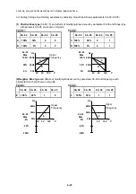
12. 03- 00~03- 05=
【
17
】
Reset
When a failure that can be manually reset occurs ,turn on a terminal with function
【
17
】
, the failure will be
reset. (Same function as the Reset button on keypad).
13. 03- 00~03- 05=
【
18
】
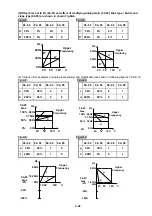
Auto _ Run Mode
When an input terminal is set to function
【
18
】
, the programmable auto- sequencer function is enabled,
Refer to description of parameter group 6.
14. 03- 00~03- 05=
【
19
】
Speed Search Stop
When starting, the inverter detects the current speed of the motor, and then accelerates from the
current speed to target speed.
15. 03- 00~03- 05=
【
20
】
Energy-saving operation
FAN, PUMP or other high inertia loads need greater starting torque, but once the operational speed is
reached they need much less torque. In this mode the output voltage to
the motor is
reduced to match
the required torque demand, hence providing a saving in energy.
The output voltage gradually declines as the input is ON. It will gradually increase (to the original
voltage)
when
the input is OFF.
Note: The acceleration an
※
d deceleration speed of energy saving operation is the same as the speed
of speed search.
16. 03- 00~03- 05=
【
21
】
Reset PID Integral value to Zero
When the extermal terminals, S1 to S6 set to 22, after turning it on then off once the counter value increases
by 1.
17) 03- 05=
【
22
】
Pulse Input
When the extermal terminals, S1 to S6 set to 22, after turning it on then off once the counter value increases
by 1.
18) 03- 00~03- 05=
【
23
】
Pulse input Counter Reset
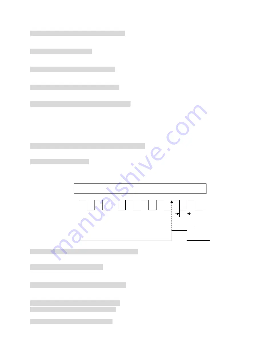
When anyone of the extermal terminals S1 to S6 set to 23 and turned on, the pulse input counter value will be
cleared, and "c0000" will be displayed.For the pulse counter to be enabled again this input must be turned off.
19 )03- 00~03- 05=
【
24
】
PLC Input
When anyone of the extermal terminals S1 to S6 set to 24 and turned on
,
the PLC program inputs will be
enabled.
20) 03- 00~03- 05=
【
27
】
Enable KEB Function
Once the KEB enable input is activated the decelleration time to stop will be according to parameter 07-14.
21) 03- 00~03- 05=
【
28
】
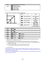
Fire Mode Function
With Software revision issued before 1.1:
¾
The firemode function is enabled when 08-17 = 1
With Software revision issued after 1.1:
¾
The firemode function works is enabled when 03-00~03-05 =
【
28
】
¾
Once fire mode is activated following takes place:-
1. The operator panel indicates FIrE
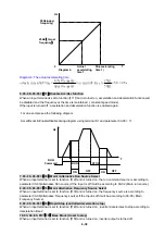
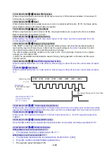
Signal output with 03-22.
count value reached.
03-22= 5 counts
Pulse Input
Multi-function input
terminal
1.5ms
c0000 c0001 c0002 c0003 c0004 c0005 c0001 c0002
Indication value
12-00=8
The trigger timing can't be less than
1.5ms.
Summary of Contents for e510 series
Page 1: ......
Page 8: ...2 1 Chapter 2 Part Number Definition 2 1 Model Part Number...
Page 13: ...3 4 Screw M4 Screw M4...
Page 34: ...3 25 c Three phase 200V 8 10HP 400V 8 15HP E510 Frame 3 E510 Frame 3 NEMA1...
Page 35: ...3 26 d Three phase 200V 15 20HP 400V 20 25HP E510 Frame 4 E510 Frame 4 NEMA1...
Page 43: ...3 34 3 5 2 Single Three phase Model 200V E510 2P5 H E510 201 H E510 202 H E510 203 H...
Page 197: ......


