background image

TECO-Westinghouse Motor Company

5100 N. IH-35

Round Rock, Texas 78681

Toll Free: 800-279-4007

Phone: 512-255-4141

Fax: 512-244-5512

www.tecowestinghouse.com

04/05

Summary of Contents for FM50101-X

Page 1: ...www tecowestinghouse com Instruction Manual User Manual...

Page 2: ...re Index 3 1 Keypad Operating Instructions 35 3 2 Parameters List 36 3 3 Parameter Function Description 37 3 4 Malfunction Indication and Countermeasure 49 3 5 General Malfunction Examination Method 5...

Page 3: ...nents on the PCB right after turning off power and before the charging indicator goes off Do not attempt to wire circuits while power is on Do not attempt to examine the components and signals on the...

Page 4: ...r unpacking your FM50 AC Drive Check to see if the model number of the AC Drive matches the model number that you ordered Check to see whether any damage occurred to the AC Drive during shipment Do no...

Page 5: ...may cause personal injury or damage to the AC drive Install the drive onto a firm metal base plate or another non flammable type material Do not install the drive on or near any flammable material An...

Page 6: ...ion is based on the setup of F_10 and the condition of external switch FWD REV button Attention the restart operation is determined by F_23 and F_24 1 When F_10 0 the AC drive will not start in restar...

Page 7: ...y adjusted and factory set before delivery CAUTION Do not proceed with disassembly or examination procedure before ensuring that the power is off and the Power LED is extinguished CAUTION AC drive amb...

Page 8: ...il grease and gas Keep away from salty environments Keep away from rain or where dripping water may get into the AC Drive Avoid dusty environments Avoid high temperature environments Avoid exessive di...

Page 9: ...as Avoid contact with corrosive gases and liquids Prevent foreign dust flecks or metal scraps from contacting the AC drive Avoid electric magnetic interference soldering or power machinery Avoid exces...

Page 10: ...in the enclosure is 122 F 50 C with Shield Sticker removed 2 2 Sample Model No Identification 10 FLUXMASTER 50 INSTRUCTION MANUAL P2 HP 1 4 03 3HP C Chassis N4 NEMA 4 OC Chassis with Filter N4FS NEMA...

Page 11: ...4 0 75 1 5 2 2 Motor HP 1 4 1 2 1 2 3 Output Current A 1 4 2 3 4 2 7 5 10 5 Rated Capacity KVA 0 53 0 88 1 6 2 9 4 0 Weight lb 2 2 2 5 5 Input Voltage Max Single Three Phase 200 240V 10 15 50 60Hz 5 O...

Page 12: ...built in braking transistor Built In Functions Decelerate or free run stop Auto reset DC braking frequency Voltage Time can be setup by constants Display Three digit 7 segment LED display frequency f...

Page 13: ...n 14 AWG 14 AWG 12 AWG 12 AWG 2 0mm2 2 0mm2 3 5mm2 3 5mm2 Terminal Screw Terminal Screw Terminal Screw Terminal Screw M3 M3 M4 M4 M4 Signal Terminal TM2 Wire Dimension 0 75 mm2 18 AWG Terminal Screw 1...

Page 14: ...To utilize external control automatic restart or breaking controller the magnetic contactor must be added at the primary side Do not operate the magnetic contact to switch ON or OFF the AC drive Power...

Page 15: ...nut holes to ensure that the metal coupling nuts and the shielding make contact with the AC drive and the motor Don t solder a conductor to the shielding Use a metal clamp to connect the shielding fr...

Page 16: ...pair cable should be used to wire the control circuitry Please refer to following diagram Connect the shield wire to the grounding terminal Connect only one end of the shield Wiring distance of 164ft...

Page 17: ...orrect diameter for primary power circuitry and control circuitry in compliance with NEC or other applicable codes 2 4 Wiring Diagram Wire Terminations to the AC drive must be made with either UL list...

Page 18: ...External 24V Supply 18 FLUXMASTER 50 INSTRUCTION MANUAL...

Page 19: ...ELAY Connection point rated capacity 250VAC 1A 30VDC 1A 3 FWD FW Operation control terminals see parameter F_03 4 REV RE 5 12V 12 Common point for terminals 3 4 6 7 6 SP1 SP Multi Function input termi...

Page 20: ...2 0 10VDC analog signal When F_11 is set to 1 2 5 Dimensions Location of Terminal Block 115V 1 4 1HP 230V 1 4 1HP models NOTE For safety reasons we strongly recommend removing the M4 grounding screw t...

Page 21: ...21 FLUXMASTER 50 INSTRUCTION MANUAL 230V 2 3HP 460V 1 3HP Dimensions Installation of Class B Filter 2 36 2 99 0 98...

Page 22: ...DIMENSIONS FM50 NEMA 4X IP65 Indoor Duty with operators 115V 230V 1 4 1HP models 22 FLUXMASTER 50 INSTRUCTION MANUAL...

Page 23: ...X units with operator devices 2 Power supply cable 14 AWG 2 0mm2 3 Motor cable 16 AWG 1 25mm2 4 Tightening torque values for terminals 1 Power Motor cable plug in terminal 4 34in lb 5kg cm 2 Remote co...

Page 24: ...nal 4 34in lb 5kg cm 2 Remote control wire 3 47in lb 4kg cm 3 Outer cover M4 5 20in lb 6kg cm 5 Input source single phase L1 L2 make sure that it is connected to the appropriate power supply 6 Output...

Page 25: ...25 FLUXMASTER 50 INSTRUCTION MANUAL CONNECTION FM50 NEMA 4X IP65 Indoor Duty 115V 230V 1 4 1HP models MOUNTING...

Page 26: ...CONNECTION FM50 NEMA 4X IP65 Indoor Duty with operators 115V 230V 1 4 1HP models MOUNTING 26 FLUXMASTER 50 INSTRUCTION MANUAL...

Page 27: ...27 FLUXMASTER 50 INSTRUCTION MANUAL DIMENSIONS FM50 NEMA 4X IP65 Indoor Duty with operators 230V 2 3HP 460V 1 3HP models...

Page 28: ...er supply cable 230V 12 AWG 3 5mm2 460V 16 AWG 1 25mm2 3 Motor cable 230V 14 AWG 2 0mm2 460V 16 AWG 1 25mm2 4 Tightening torque values for terminals 1 Power Motor cable TM1 TM3 Terminal 6 94in lb 8kg...

Page 29: ...2 Remote control wire 3 47in lb 4kg cm 3 Outer cover M4 5 20in lb 6kg cm 5 Input source single phase or three phase L1 L2 L3 ensuring that it is connected to a 200 230V or a 400 460V supply Models FM...

Page 30: ...waterproof conformed IP65 ferrite core QTY 1 of metal fastener QTY 1 of MF Zin 5 C screw CAUTION If the EMC regulation must be met constrain the motor cables with the ferrite core onto the motor cable...

Page 31: ...31 FLUXMASTER 50 INSTRUCTION MANUAL CONNECTION FM50 NEMA 4X IP65 Indoor Duty with operators 230V 2 3HP 460V 1 3HP models...

Page 32: ...EMC MOUNTING NEMA 4X IP65 Indoor Duty with operators 230V 2 3HP 460V 1 3HP models 32 FLUXMASTER 50 INSTRUCTION MANUAL...

Page 33: ...33 FLUXMASTER 50 INSTRUCTION MANUAL 2 6 Mounting Instructions...

Page 34: ...sh the DIN rail forward until the middle rib grips firmly with back panel Step1 Use a small screwdriver inserting it into the middle rib of DIN rail and press the screwdriver in order to remove the DI...

Page 35: ...ription CAUTION To avoid damage do not operate keypad by screwdriver or other sharp ended tool Keypad Operation Flowchart Note 1 Displays setting of frequency when stopped Displays output frequency wh...

Page 36: ...eypad 1 0 1 0 41 1 Terminal TM2 0 Keypad Frequency Control 11 1 Terminal 0 10V 0 20mA 1 0 2 0 41 2 Terminal 4 20mA Carrier frequency 12 Carrier Frequency Setting 1 1 5 5 42 4 Control 1 10 4 Torque Com...

Page 37: ...requency 0 1Hz 1 0 200Hz 30 48 4 Power Up Start 28 0 Enable 1 0 1 1 48 4 1 Disable Software Version 29 CPU program version 48 Fault Log 30 Fault log for three faults 48 NOTE 1 Parameters that can be a...

Page 38: ...ored when F_22 1 Reverse lockout F_04 Motor Rotation Direction Setting 0 Forward 1 Reverse Although there is no Forward Reverse pushbutton on the digital control panel it is possible to adjust forward...

Page 39: ...er to the following tables Specification 50Hz System Application General Application High Starting Torque Decreasing Torque F_5 1 2 3 50Hz System V F pattern Specification 60Hz System Application Gene...

Page 40: ...on input setting and the multi function input terminal is ON the inverter operates at SP1 frequency F_08 2 When F_19 or F_20 1 multi function input setting and the multi function input terminal is ON...

Page 41: ...external frequencies F_11 Frequency Control 0 Keypad 1 Analog Speed PotTerminal TM2 0 10V 0 20mA 2 Analog Speed PotTerminal TM2 4 20mA NOTE 1 If the jog when start stop control is set to keypad run or...

Page 42: ...ing its operation it is possible that the switching of the high carrier frequency may interfere with external electronic components or other controllers or even cause vibration in the motor Adjusting...

Page 43: ...electronic thermal overload protection for the motor is as follows 1 Motor rated current AC drive rated current x F_18 F_18 Motor rated current AC drive rated current 2 When the load is within 100 of...

Page 44: ...ration push RESET button or activate an external reset contact wired to Terminal 2 F_19 Multi Function Input Terminal 1 1 5 1 6 CPU version v1 9 and above F_20 Multi Function Input Terminal 2 1 5 1 6...

Page 45: ...the emergency stop 4 F_19 F_20 4 External Base Block Immediate Shut Down When the external base block signal is activated the AC drive output will be immediately shut off ignoring the stopping method...

Page 46: ...will stop immediately If the voltage level recovers within 2 seconds the AC drive can restart by using its speed search program 2 When F_23 0 1 If the momentary power loss is less than 2 seconds the A...

Page 47: ...tTimes 0 5 1 When F_24 0 the AC drive will not auto restart after a fault recovery Except for momentary power loss please refer to F_23 for details 2 When F_24 1 5 the AC drive will resume operation v...

Page 48: ...t three faults 1 Last three faults indicate the sequence of the occurrence of faults by the location of decimal point x xx indicates a recently occurred fault xx x indicates the prior fault event xxx...

Page 49: ...rn the AC drive for repair operating AC drive over 1 Detection circuit defective 1 Return the AC drive for repair OH heat while not 2 Environment overheat or 2 Improve ventilation operating poor venti...

Page 50: ...ation setting too short Adjust to a longer acceleration time deceleration OCb Overcurrent DC Braking frequency braking voltage Adjust to reduce settings of DC Braking at braking or braking time settin...

Page 51: ...signal is activated through E S stop the multi function input terminal the AC drive decelerates and stops E S flashes after AC drive stops Refer to instruction for F_19 for detail When the external BA...

Page 52: ...1 T2 Correct with motor rotation direction setting Motor runs in and T3 correct Fn_04 or FWD REV key opposite direction Is the wiring for the forward and reverse Wiring should be in accordance with th...

Page 53: ...4 Troubleshooting Procedures 53 FLUXMASTER 50 INSTRUCTION MANUAL 4 1 Flow Chart...

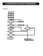
Page 54: ...FLUXMASTER 50 INSTRUCTION MANUAL Continued 54...

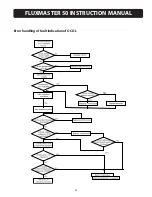
Page 55: ...FLUXMASTER 50 INSTRUCTION MANUAL Error handling of fault indication of OC OL 55...

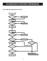
Page 56: ...Error handling of fault indication of OV LV 56 FLUXMASTER 50 INSTRUCTION MANUAL...

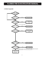
Page 57: ...57 FLUXMASTER 50 INSTRUCTION MANUAL 1 Motor inoperative...

Page 58: ...FLUXMASTER 50 INSTRUCTION MANUAL 58 2 Motor overheat...

Page 59: ...FLUXMASTER 50 INSTRUCTION MANUAL 3 Unstable motor operation 59...

Page 60: ...f the primary Measure voltage by Voltage level conforming Improve input Source Voltage circuitry normal multi meter specification power source AC Drive Are the tightened parts secured Visual inspectio...

Page 61: ...mount of residual charge in the internal capacitors 1 Clean out internal dust and dirt 2 Check mounting screws on every terminal and part Tighten loose screws 3 Dielectric strength test a Remove all c...

Page 62: ...ent MEASUREMENT MEASURING POINT INSTRUMENT NOTE MEASUREMENT CRITERION Input Voltage Moving iron VI Input Current Moving iron Ii Input Power Power meter P W1 Pi Input Power Factor Calculate power facto...

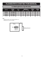
Page 63: ...DIN 201 5 12 x 2 83 x 0 30 ALL FM50 MODELS 4 7 of Braking Resistor and Input Reactor Specification Braking Braking Braking Braking Input AC Reactor Model Transistor Resistor Torque Resistor Current In...

Page 64: ...stor HP of Braking Resistor Resistor Torque Model W ED FM50 202 FM100 2BR2 2 150 100 10 119 FM50 203 FM100 2BR3 3 200 70 9 116 FM50 401 FM100 4BR1 1 60 750 8 125 FM50 402 FM100 4BR2 2 150 400 10 119 F...

Page 65: ...MANUAL Customer Model Application Telephone Address F_ Value Setting F_ Value Setting F_ Value Setting F_00 F_11 F_22 F_01 F_12 F_23 F_02 F_13 F_24 F_03 F_14 F_25 F_04 F_15 F_26 F_05 F_16 F_27 F_06 F...

Page 66: ...Notes 66 FLUXMASTER 50 INSTRUCTION MANUAL...

Page 67: ...Notes 67 FLUXMASTER 50 INSTRUCTION MANUAL...
Page 68: ...TECO Westinghouse Motor Company 5100 N IH 35 Round Rock Texas 78681 Toll Free 800 279 4007 Phone 512 255 4141 Fax 512 244 5512 www tecowestinghouse com 04 05...

Reviews: