background image

14                                             


Chapter 2 Wiring 

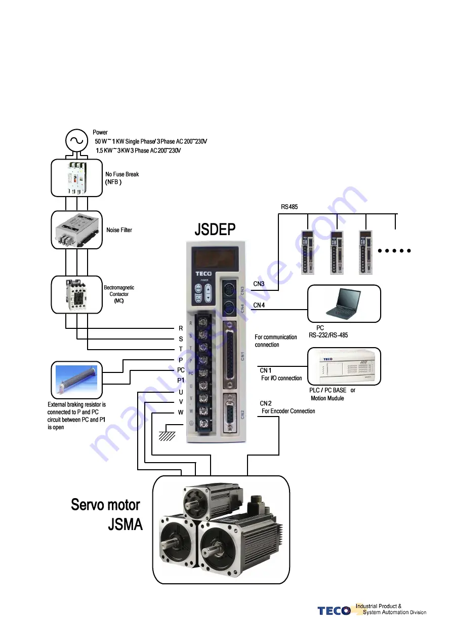
2-1 Basic Wiring for Servo System 

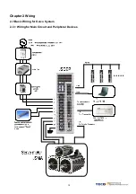
2-1-1 Wiring for Main Circuit and Peripheral Devices 


Summary of Contents for JSDEP Series

Page 1: ...atching up machine to change the user parameter setting before machine performs If there is no according correct setting number it could lead to out of control or breakdown Safety proceeding Check the...

Page 2: ...ng and procedure of assembly line Controller procedure for digital board status displaying unusual alarm and strategy explanation Servo System control function running testing and procedures adjusted...

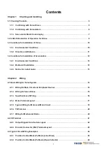
Page 3: ...Method of Installation 12 1 4 3 Notice for in stall motor 13 Chapter 2 Wiring 2 1 Basic Wiring for Servo System 14 2 1 1 Wiring for Main Circuit and Peripheral Devices 14 2 1 2 Wiring for Servo Drives...

Page 4: ...ter 3 Panel Operator Digital Operator 3 1 Panel Operator on the Drives 30 3 2 Trial Operation for Servomotor without Load 31 Chapter 4 Parameter Function 4 1 Explanation of Parameter Groups 32 4 2 Par...

Page 5: ...portation do not power ON Check if there are any bad assembly or slipped component in the Servo Drive and Motor Check if the Motor s rotor and shaft can be rotated smoothly by hand The Servo Motor wit...

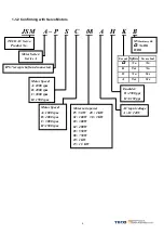
Page 6: ...Series Series A Motor Speed A 1000 rpm B 2000 rpm C 3000 rpm H 1500 rpm Motor Speed A 1000 rpm B 2000 rpm C 3000 rpm H 1500 rpm Encolder B 2500 ppr H 8192 ppr Motor ratio power P5 50 W 20 2 KW 01 100...

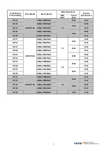
Page 7: ...LC03AB JSMA PLC03AB 2500 H0122 H1122 JSMA LC03AH JSMA PLC03AH 0 3 3000 8192 H1141 JSMA SC04AB 2500 H0142 JSMA SC04AH 0 4 Rated 3 5A 3000 8192 H1151 JSMA PSC04AB 2500 H1152 JSDEP 15A JSMA PSC04AH 0 4 R...

Page 8: ...1 0 3000 8192 H1511 JSMA PMA15AB 2500 H1512 JSMA PMA15AH 1000 8192 H1521 JSMA PMB15AB 2500 H1522 JSMA PMB15AH 2000 8192 H1531 JSMA PMC15AB 2500 H1532 JSMA PMC15AH 1 5 3000 8192 H1541 JSMA PMB20AB 2500...

Page 9: ...Speed control for the servo motor can be achieved via parameters set within the controller or from an external analog 10 10 Vdc command Control of the internal speed parameters is via the Digital Inpu...

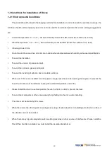
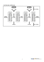
Page 10: ...ase and salt To avoid the corrosive gases and liquids To avoid the invading of airborne dust or metallic particles When over 1 Drives are installed in control panel enough space have to be kept to get...

Page 11: ...11 1 3 2 Direction and Distance Over 30mm Over 25mm Over 30mm Over 25mm Over 25mm Air flow Air flow Over 10mm Over 10mm Fan Fan...

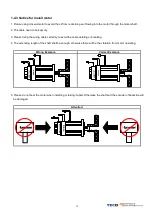
Page 12: ...rne dust or metallic particles Do not mount the servo motor in a location where temperatures and humidity will exceed specification Do not mount the motor in a location where it will be subjected to h...

Page 13: ...3 Please fixing the wiring cable certainly to avoid the cable ablating or breaking 4 The extending length of the shaft shall be enough otherwise there will be the vibration from motor operating Wrong...

Page 14: ...14 Chapter 2 Wiring 2 1 Basic Wiring for Servo System 2 1 1 Wiring for Main Circuit and Peripheral Devices...

Page 15: ...t be correctly connected otherwise it can not output signal and cause the protect loop of emergency stop abnormal Please do these below to avoid the wrong operation from noise Please install devices s...

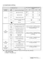
Page 16: ...7 General Analog Input 18 25 43 General Analog Output 45 46 48 49 24V Power I O Ground 0 2mm or 0 3mm Twisted pair cable connecting to the I O Grounding wire including shield cable 14 17 41 Position C...

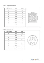
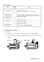
Page 17: ...2 Military Specifications Joint No Brake Terminal Color Signal A Red U B White V C Black W D Green FG A B D C 3 Military Specifications Joint Brake Terminal Color Signal B Red U G White V E Black W C...

Page 18: ...l Color Signal 1 White 5V 2 Black 0V 3 Green A 4 Blue A 5 Red B 6 Purple B 7 Yellow Z 8 Orange Z 9 Shield FG 2 Military Specifications Joint Terminal Symbol Color Signal B White 5V I Black 0V A Green...

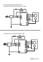
Page 19: ...of Single Phase Main Power Less than 1KW The Wiring Example of 3 Phase Main Power More than 1KW R S T PC P FG W V U 3 Phase 220V R TB1 TB1 NFB MC M PG FG Red White Black Green External Regeneration B...

Page 20: ...wer input terminal T Connecting to external AC Power Single 3 Phase 200 230VAC 10 15 50 60Hz 5 External regeneration resistance terminal P Regeneration terminal common point PC Please refer to Cn012 t...

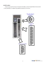
Page 21: ...control signal terminal CN1 encoder terminal CN2 and communication connector CN3 CN4 The diagram below displays all positions for the terminal CN1 connector Male CN2 connector Male CN3 CN4 Female Com...

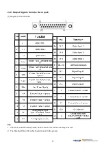
Page 22: ...tput Signals from the Servo pack 1 Diagram of CN1 Terminal P S 1 If there is unused terminal please do not connect it or let it be the relay terminal 2 The Shielded Wire of I O cable should connect to...

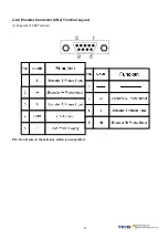
Page 23: ...23 2 2 2 Encoder Connector CN2 Terminal Layout 1 Diagram of CN2 Terminal P S Do not wire to the terminal which is un operated...

Page 24: ...erminal Layout 8 6 3 5 1 2 1 RxD Serial data receive 2 3 GND Ground 4 TxD Serial data transmission 5 Data Serial data transmission 6 7 Data Serial data transmission 8 1 2 3 4 5 Data Serial data transm...

Page 25: ...25 2 3 Typical Circuit Wiring Examples 2 3 1 Position Control Mode Pe Mode Line Driver Pe mode External pulse positioning command...

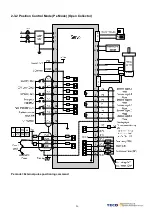
Page 26: ...26 2 3 2 Position Control Mode Pe Mode Open Collector Pe mode External pulse positioning command...

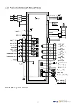
Page 27: ...27 2 3 3 Position Control Mode Pe Mode Pi Mode Pi mode Internal position command...

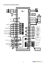
Page 28: ...28 2 3 4 Speed Control Mode S Mode...

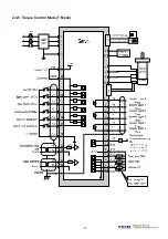
Page 29: ...29 2 3 5 Torque Control Mode T Mode...

Page 30: ...power capacitors are discharged complete Do NOT wire or assemble to the servo drive before Charge LED is off Key Name Function Keys Description MODE SET 1 To select a basic mode such as the status dis...

Page 31: ...ation B Purpose of trial run P ow er W ining P ow er W ining P ow er W ining P ow er W ining S V S V S V S V M otor M otor M otor M otor M otor Table M otor Table M otor Table M otor Table C onnect to...

Page 32: ...ion Un xx Status Display Parameters dn xx Diagnostics Parameters AL xx Alarm Parameters Cn 0xx System Parameters Tn1xx Torque Control Parameters Sn2xx Speed Control Parameters Pn3xx Position Control P...

Page 33: ...and is set to 100 Un 13 External CW Torque LimitCommand Value Ex Display 100 Means current external CW toque limit command is set to 100 Un 14 Motor feed back Less then 1 rotation pulse value Low Byte...

Page 34: ...ue command is 50 of rated torque Un 29 Load inertia x0 1 When Cn002 2 0 Auto gain adjust disabled it displays the current preset load inertia ratio from parameter Cn025 When Cn002 2 1 Auto gain adjust...

Page 35: ...function SON is enabled when Power on 0 X 0 1 CCWL CWL Input contact function Setting Explanation 0 CCWL and CWL input contacts are able to control the drive inhibit of CCW and CW Cn002 1 1 CCWL CWL...

Page 36: ...al logic level status 1 ON 0 OFF Refer to section5 6 1 for setting contact the high Low logic levels 0 msec 2000 2000 511H 0003H Motor rotate direction Inspect from the load side CCW CW When Torque or...

Page 37: ...on is 2000 ppr If you setting Cn005 1000 the output is 1000ppr Encoder pulse per rotation pulse 1 Encoder pulse per rotation 513H 0005H Cn006 Reserve Speed reached preset Cn007 Speed preset level for...

Page 38: ...rvo model 0 W 0 10000 51AH 000CH Frequency of resonance Filter Notch Filter Cn013 Enter the vibration frequency in Cn013 to eliminate system mechanical vibration 0 Hz 0 1000 C40H 000DH Band Width of t...

Page 39: ...ntrol is selected If Position error value is greater than Cn019 P control is selected 0 pulse 0 50000 C4EH 0013H Automatic gain 1 2 switch delay time Cn020 Speed loop 2 to speed loop 1 Change over del...

Page 40: ...in 1 is selected When position error value is greater than Cn024 Gain 2 is selected When Gain 2 is active and position error value becomes less than Cn024 system will automatically switch back to Gain...

Page 41: ...unning Cn031 3 Disabled 0 X 0 3 Low Voltage Protection AL 01 auto reset selection This parameter AL 01 could be set the method of Low Voltage Protection Setting Explanation 0 As servo on it shows AL 0...

Page 42: ...RS 232 braud rate setting Setting Explanation 0 4800 1 9600 2 19200 Cn037 1 3 38400 1 bps 0 3 Communication RS 485 selection This parameter can be set to RS 485 communication written to the EEPROM or...

Page 43: ...ccel decel time Constant 0 X 0 1 520H 0101H Linear accel decel time period Tn102 Time taken for the torque command to linearly accelerate to the rated torque level or Decelerate to zero torque 1 msec...

Page 44: ...imit 2 As follows Input Contact SPD2 Input Contact SPD1 1 0 Note Input contacts status 1 ON and 0 OFF Refer to 5 6 1 to set high or low input logic levels 200 rpm 0 3000 527H 0106H Preset Speed Limit...

Page 45: ...5 6 1 to set high or low input logic levels 200 rpm 4500 4500 537H 0202H Internal Speed Command 3 Sn203 In Speed control input contacts SPD1 and SPD2 can be used to select 3 sets of internal speed co...

Page 46: ...function then set the time period for the speed to rise to 63 2 of the full speed 1 msec 1 10000 52BH 0206H Speed command linear accel decel time constant Sn207 Set Sn205 2 to enable this function the...

Page 47: ...210 Refer Sn208 200 msec 0 5000 C46H 020AH Speed loop Gain 1 Sn211 Speed loop gain has a direct effect on the frequency response bandwidth of the Speed control loop Without causing vibration or noise...

Page 48: ...t contact ZS is activated 50 rpm 0 4500 532H 020FH Analog Speed Command Ratio Sn216 Slope of voltage command Speed command can be adjusted 10 5 5 10 Input Voltage V Slope set by Sn216 4500 3000 1500 4...

Page 49: ...select one of four electronic Gear Ratio Numerators To select Numerator 1 the statue of the input contacts GN1 GN2 should be as follows Input Contact GN2 Input Contact GN1 0 0 Note Input contacts stat...

Page 50: ...rror value is higher then number of pulses set in Pn308 an Alarm message AL 11 Position error value alarm will be displayed 50000 pulse 0 50000 556H 557H 0308H Incorrect position Error band lower limi...

Page 51: ...ction Definition CCW CW Setting Explanation 0 CW Clockwise Pn314 1 CCW Counter Clockwise 1 X 0 1 55DH 030EH Pulse Error Clear Modes Setting Explanation 0 Once CLR signal is activated it eliminates the...

Page 52: ...or Home Position switch in 1 st speed in CCW direction Input contacts CCWL or CWL can be used as the Home Reference Switch Once Home reference switch is detected then input Contacts CCWL and CWL will...

Page 53: ...osition in 1 st speed in CW direction and sets the Home reference position as soon as the nearest Z marker pulse is detected When using this function set Pn365 1 2 After setting the Z Phase to be the...

Page 54: ...direction in 2 nd speed to detect the Home Position again then it decelerates and stops Pn317 3 1 After detecting the Home signal it sets this position to be the Home reference Un 14 encoder feed back...

Page 55: ...nal position command input When position command input switch to external position pulse the speed and acceleration are already constant so it doesn t use the S curve time constant generator Notes 1 R...

Page 56: ...0 Pi 56DH 0708H Internal Position Command 3 Rotation Number Pn407 Please refer to Pn401 0 rev 16000 16000 Pi 570H 0709H Internal Position Command 3 Pulse Number Pn408 Please refer to Pn402 0 pulse 131...

Page 57: ...Command 9 Pulse Number Pn426 Please refer to Pn402 0 pulse 131072 131072 Pi 58AH 58BH 0722H 0723H Internal Position Command 9 Move Speed Pn427 Please refer to Pn403 0 rpm 0 3000 Pi 589H 0724H Interna...

Page 58: ...nternal Position Command 15 Move Speed Pn445 Please refer to Pn403 0 rpm 0 3000 Pi 5A1H 073CH Internal Position Command 16 Rotation Number Pn446 Please refer to Pn401 0 rev 16000 16000 Pi 5A4H 073DH I...

Page 59: ...tion Command 22 Rotation Number Pn464 Please refer to Pn401 0 rev 16000 16000 Pi 5BCH 0755H Internal Position Command 22 Pulse Number Pn465 Please refer to Pn402 0 pulse 131072 131072 Pi 5BEH 5BFH 075...

Page 60: ...ion Command 28 Pulse Number Pn483 Please refer to Pn402 0 pulse 131072 131072 Pi 5D6H 5D7H 076EH 076FH Internal Position Command 28 Move Speed Pn484 Please refer to Pn403 0 rpm 0 3000 Pi 5D5H 0770H In...

Page 61: ...Position Command 32 Rotation Number Pn494 Please refer to Pn401 0 rev 16000 16000 Pi 5E4H 077DH Internal Position Command 32 Pulse Number Pn495 Please refer to Pn402 0 pulse 131072 131072 Pi 5E6H 5E7...

Page 62: ...s 1 500 Pi Pe S 531H 0402H Speed Loop Gain 2 Same function as Sn213 qn503 Refer to qn401 40 Hz 10 450 Pi Pe S 53AH 0403H Speed Loop Integration Time Constant 2 Same function as Sn214 qn504 Refer to qn...

Page 63: ...osition Hold 14 SHOME Start Home 15 ORG Home Position Reference Origin 16 POS1 Internal Position select 1 17 POS2 Internal Position select 2 18 POS3 Internal Position select 3 19 POS4 Internal Positio...

Page 64: ...efer to Hn601 X 001 11F ALL C26H 0504H DI 5 Hn605 Plearse refer to Hn601 X 001 11F ALL C27H 0505H DI 6 Hn606 Plearse refer to Hn601 X 001 11F ALL C28H 0506H Hn607 Reserve Hn608 Reserve Hn609 Reserve H...

Page 65: ...Turret mode Hn613 0 Hn613 1 0E P6 Position Display 6 for Tool Turret mode Refer to the cross reference table on page 77 X 01 0E ALL DO 1 Active Level Setting Explanation 0 Close when the output is ac...

Page 66: ...3 0003 0003 0003 0003 0003 0003 0016 0016 0016 0016 0003 Hn 604 0104 0104 0104 0104 0104 0104 0017 0017 0017 0017 0104 Hn 605 0105 0105 0105 0105 0105 0105 0018 0018 0018 0018 0105 Hn 606 001B 0006 00...

Page 67: ...et by input signal Once the cause of Alarm is rectified disable SON signal Switch off Servo ON then activate input signal ALRS Alarm condition should be cleared and the drive will be ready for operati...

Page 68: ...d Turn ALRS DI ON 1 1 0 0 04 Drive Over current Reset Power Supply 1 0 1 1 05 Encoder ABZ phase signal error Reset Power Supply 1 0 1 0 06 Encoder UVW phase signal error Reset Power Supply 1 0 0 1 07...

Reviews: