N3 Drive Operations Manual
Power Terminal Designations & Ratings (TM1)
10
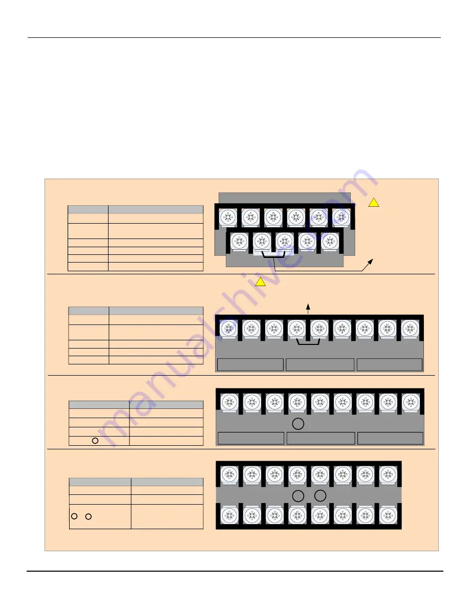
7.0 Power Terminals Designations and Ratings (Terminal Block TM1)
Depending on inverter ratings, the power terminals (TM1) can have one of three configurations. These are shown as
A), B), C) and D) in Fig. 7.1. Section 7.2 covers the electrical ratings and tightening torques of the terminals.
Do Not
over tighten terminal screws. (See Sec. 7.2)
Use the proper wire size for terminal connections.
Use proper termination techniques.
7.1 Power Terminal Configuration TM1
R
/L1
S
/L2
T
/L3
B1/P
_
B2
U
T1
V
T2
W
T3
Power
Dynamic
To Motor
230V 3Ø: 15
– 20 HP
460V 3Ø: 20 HP
R
/L1
S
/L2
T
/L3
_
U
T1
V
T2
W
T3
+
230V 3Ø : 25 - 40 HP
460V 3Ø : 25 - 75 HP
Fig.7.1 Power Terminal Configuration TM1
Terminal Connections
R/L1
– S/L2 – T/L3
U/T1
– V/T2 – W/T3
B1/P
– B2
B1/P
–
_
Terminal Connections
– _
+
External DC Supply
Or External Braking
Unit.
230V 3Ø: 0.5
– 2 HP
460V 3Ø: 1
– 2 HP
230V 1Ø: 0.5
– 1 HP
Terminal Connections
(L)
– (N)
L1
– L2 – L3
T1
– T2 – T3
P1
– BR
P1
– P
*
PE
A)
C)
D)
TM1
TM1
TM1
Do Not remove the
Factory Installed
Jumper between
Terminals P
– P1
unless a DC reactor
is being installed.
CAUTION
230V 3Ø: 0.5
– 2 HP
460V 3Ø: 1
– 2 HP
230V 1Ø: 0.5
– 1 HP
3Ø Motor Output
Braking Resistor Connection
DC Reactor Connections
Earth Ground
3Ø Input Power
3Ø Motor Output
Braking Resistor
External DC Supply
R/L1
– S/L2 – T/L3
U/T1
– V/T2 – W/T3
3Ø Input Power
3Ø Motor Output
L1(L)
L2
L3(N)
T1
T2
T3
PE
PE
BR
P
P1
(L)
– (N)
L1
– L2 – L3
T1
– T2 – T3
P1
– BR
P1
– P
*
230V 3Ø: 3
– 10 HP
460V 3Ø: 3
– 15 HP
230V 1Ø: 2
– 3 HP
3Ø Motor Output
Braking Resistor Connection
DC Reactor Connections
Terminal Connections
L1
L2
L3(N)
P1
BR
T1
T2
T3
Power
Dynamic
To Motor
P
TM1
230V 3Ø: 3
– 10 HP
460V 3Ø: 3
– 15 HP
230V 1Ø: 2
– 3 HP
B)
Do Not remove the Factory Installed Jumper between
Terminals P
– P1 unless a DC reactor is being installed.
CAUTION
!
!
*
*


