Tecomat Foxtrot – system design
8/32
B1
B2
B3
B4
B5
B6
B7
B8
B9
G
N
D
D
I0
D
I1
D
I2
D
I3
D
I4
DIGITAL/SPECIAL INPUTS
DIGITAL/ANALOG INPUTS
A
I0
D
I5
A
I1
D
I6
A
I2
D
I7
A
I3
+24 V
0V
pulzní
vstup 1
pulzní
vstup 3
pulzní
vstup 2
pulzní
vstup 4
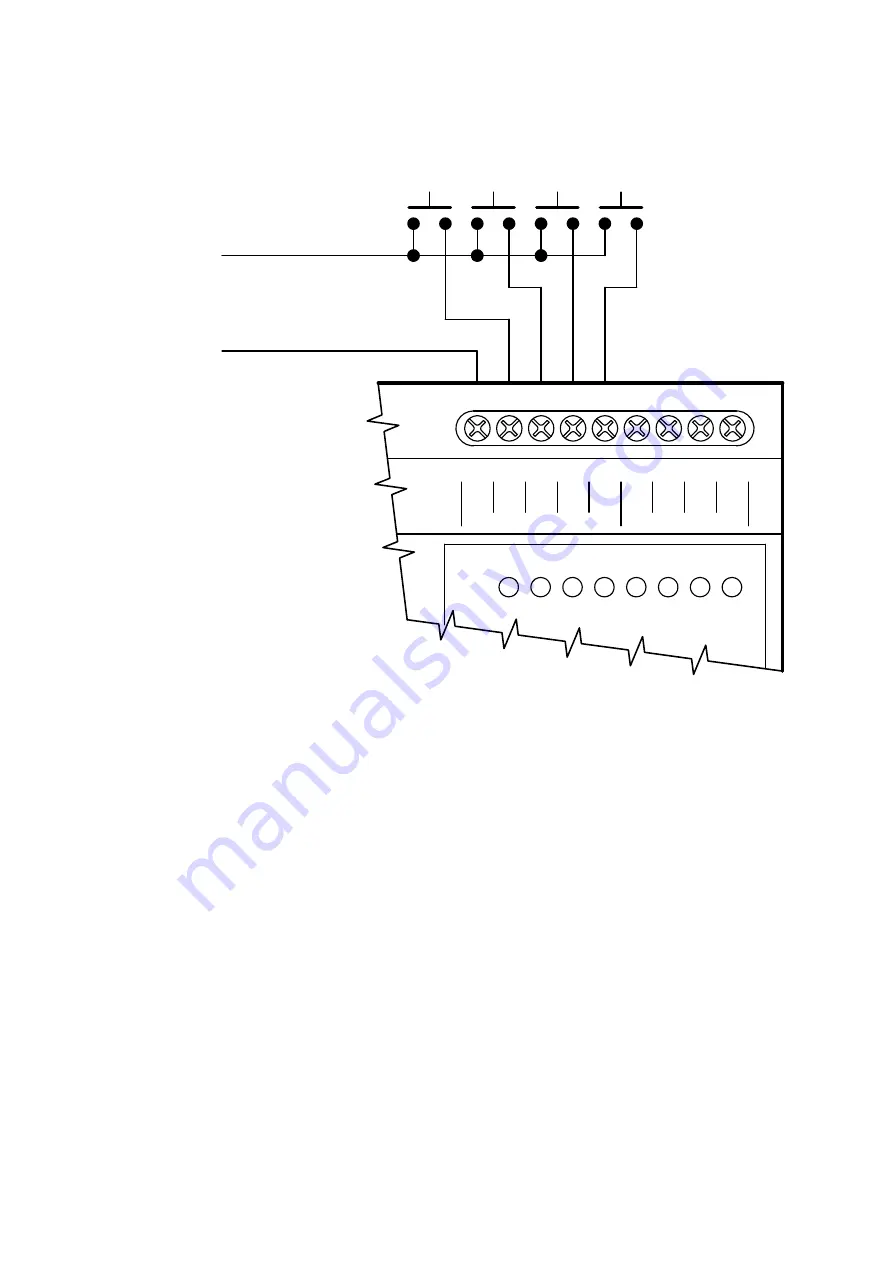
Figure 1.1.2.2 Connection example of a scanner with pulse outputs (for counters 1 to 4)
Notes for connection:
1.
The inputs are realized as fixed with common pole – (terminal GND – ATTENTION! – the
terminal is galvanically connected with the negative terminal of power supply and signal
ground of the interfaces TCL2, CIB and CH1).
2.
The inputs require connection with a pulse output (with bounce treatment).
Pulse Pulse Pulse Pulse
input 1 input 2 input 3 input 4


