Trial Run
Troubleshooting 6-8
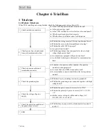
3.5.3
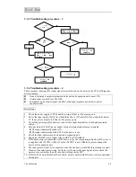
Troubleshooting procedure - 3
3.5.4
Troubleshooting procedure - 4
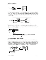
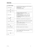
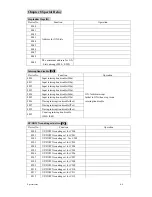
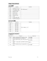
This procedure is designed for input signal error which can not be detected by CPU self-diagnose.
Error example:
z
None of input and output terminals on basic unit and expansion unit can set ON.
z
Certain input can not be set ON/OFF.
z
Sometimes a given input signal can affect other input signals on same basic unit or
expansion unit.
Resolution
1.
Check the power supply of TP03 and the wiring. If that is OK, please go on.
2.
As for the input signal, the ON level should be above 15V while OFF level should be below
9V. If not, please modify it. If that is OK, please go on.
3.
Cut all the power supply for devices connected to input terminal (as switch and proximity
switch…).
4.
Add an ex24vDC power supply to input terminal and common terminals.
z
The input indicator should be ON.
z
The input indicator should be OFF as the power is cut.
5.
Check the input indicator on basic unit and expansion unit.
6.
Supervise ON/OFF state of input relays with PC or PDA linked.
7.
If the above state is normal, that is OK (that is to say, the responding indicator will be on as it
is supplied with +24VDC, while off as the +24VDC is cut). Otherwise, please change the
basic unit or expansion unit.
8.
The input point will not act as expected when the electronic switch has large leakage current.
9.
If none of the said item is wrong, but there is still error with input signal, please check the
noise source or whether there has conductive thing inside PLC.
10.
If there still be a problem after above check, please contact with after-sale service department
for support.

