Chapter 2 Basic Unit Specification
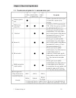
3. Communication ports
2-11
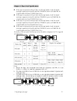
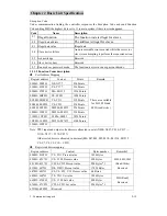
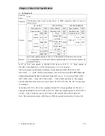
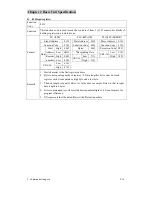
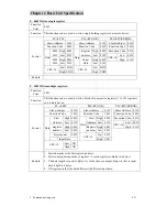
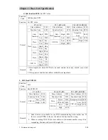
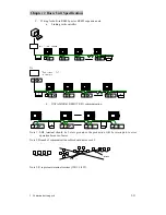
Note 5: It is necessary to add terminal resistor (120
Ω
,1/4W) when several PLCs are connected in
the Net.
Note6: The modified data for D8320 will take effect at the next scan time after communicaton
finished.
Note 7: The modified setting for D8120 will take effect at the next scan time after communicaton
finished.
Note8: When using two communication port,can’t set baud rate at 307.2k at the same time.
Note9: When using DLINK,RMIO,can’t set 7 bit mode of the Data Length.
3.3
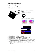
Three communication ports description
3.3.1
Modbus slave communication
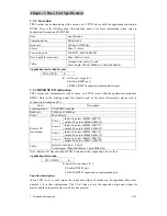
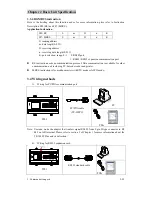
PC/PDA communication port (built-in), RS485or RS232 expansion cards (optional) and RS485
communication port (built-in only on H type), all the three port can set up Modbus slave
communication net simultaneously or respectively.
3.3.1.1
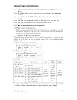
Format for Modbus slave communication
When TP03 receives command from PC, TP03 will perform according to the command and then
feedback to PC. If there is an error in command content, TP03 will feedback an exception
response to PC.
z
Command format and response format:
CRC range
Slave
Address
Function
Code
Data CRC-16
z
Response format for exception:
CRC range
Slave
Address
Function
Code
Exception
Code
CRC-16
Description
Slave Address:
Function Code
Data
CRC-16
check
Exception
Code
00H: broadcast to
all slaves
01H: read coil
01H: No.1 slave
A. 05H: write a single coil
0FH: No.15 slave
B. 0FH: write several coils
10H: No.16 slave
C. 03H: read register
….
D. 06H: write a single register
0FFH: No.255 slave E. 10H: write several registers
F.
08H:
diagnose
G.
6CH:
TP03
control
H. 01H: read TP03 ID
Data
range
differs for
various
functions
CRC range
includes
Slave
Address,
Function
Code and
Data
/Exception
Code
。
See the
respective
function
hereafter.
Note: Responding time (Time out) at computer side covers the duration for transmitting max 256
bytes (which are varies with different baud rate) pulsing waiting time in PLC scan time.


