Chapter 3 Expansion unit specification
expansion unit
3-18
2.4
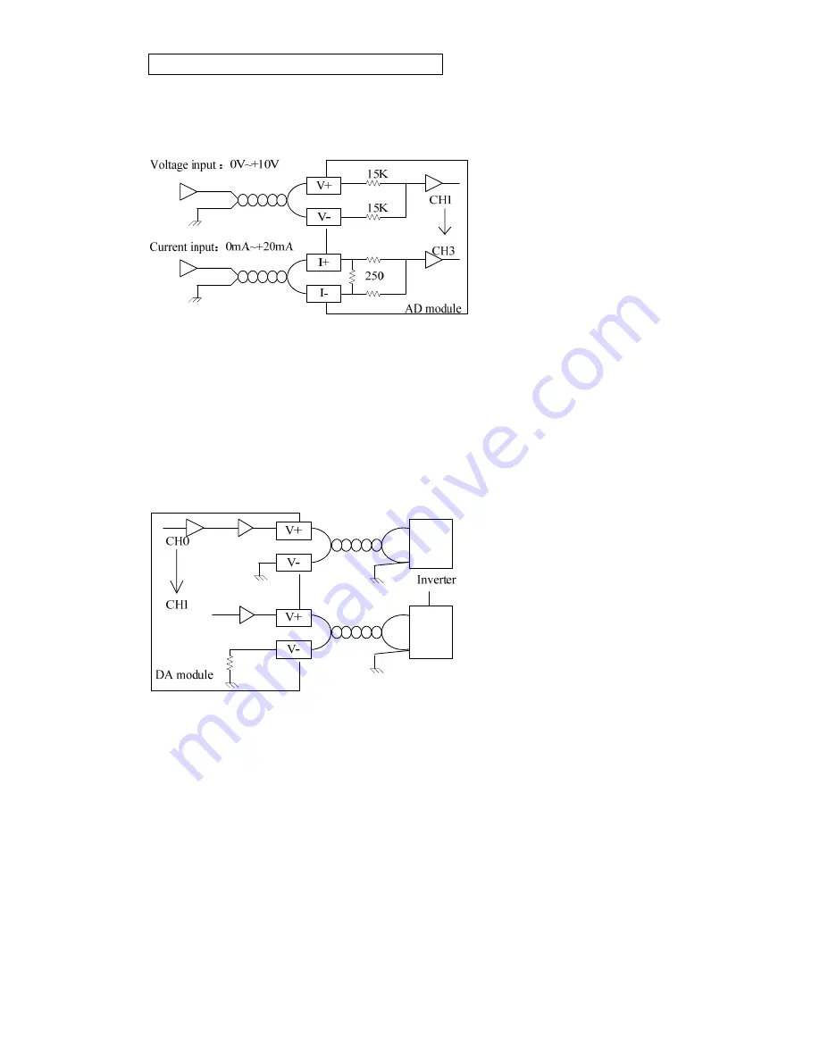
Wiring for analog expansion module
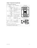
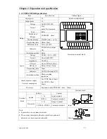
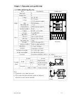
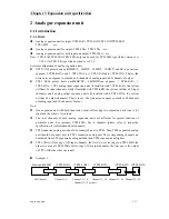
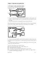
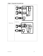
Wiring figure of Input (A/D) analog expansion module:
1. The cable for analog input should be standard isolated twisted cable, routed away power line
and other line which will interrupt others. It is recommended that the cable should be less that
3m in length.
2. Connect the common terminal to system ground. Then properly ground the system.
Both voltage signal and current signal are available for analog units. However the signal should be
less than ±15V or ±30mA with the switch properly set or the analog unit will be damaged.
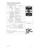
Wiring figure of Output (D/A) analog expansion module:
1. The cable for analog input should be standard isolated twisted cable, routed away power line
and other line which will interrupt others. It is recommended that the cable should be less that 3m
in length.
2. The improper wiring will lead to error operation or damage the unit. Short circuit the voltage
output will irrevocably destroy the unit.
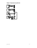
You can set voltage output or current output for the unit.
:
Keep the wire from the shield as short as possible (30mm or less).
Connect SHLD terminal with shield-net.
Connect Flame ground (FG) and SHLD terminal with wire of apx. 1.25mm
2
.
Use this module dedicated constant-voltage supply or 24VDC power supply of basic
module for the 24VDC input power supply.


