background image

4

WARNING

Read the instructions in this manual carefully

. Tecomec S.p.a. is not responsible for 

problems generated by negligence of users, by no respect of the instructions written on 
this manual and for damages caused by careless usage.

  SAFETY INSTRUCTIONS

Comply with the specified power supply voltage 

(

12V 

  ±10%

)

.

Never expose the equipment to jets of water.
Never use solvents or petroleum spirit for cleaning the outside parts of the container.
In case of electric arc welding, make sure that the power supply to the switch box is disconnected; if 
necessary disconnect the tractor battery wires.
Use only original 

Tecomec/Geoline

 parts or accessories.

INTENTED USE

This equipment is projected for installations on agricoltural spraying machines. 

NOTA:

all instructions and technical features given here below refer to products that Tecomec S.p.a. is

distributing at the time when this manual has been printed. To follow the standard product evelopment, 
Tecomec S.p.a. reserves the right to modify and update this manual at any time and without notice.

USAGE AND STORAGE OF THE INSTRUCTION MANUAL

Reproduction of any part of this publication without the authorisation of the manufacturer (Tecomec S.p.A.) 
is forbidden.
The instruction manual forms an integral part of the control panel and must be kept in a safe place which 
enables it to be consulted promptly whenever needed.
This manual also becomes an integral part of the documentation of the equipment on which the control 
panel is installed.

TECHNICAL FEATURES AND PERFORMANCE

Description

Data

Power supply voltage

12V 

  ±10%

Oparating temperature

+5°C  ÷  +60°C


INSTALLATION

Switch box

Fix the box close to the driving seat, in a clearly visible but protected position, using the bracket pro-
vided. provided. The switch box must be easy to reach by the operator and has not to restrict the view 
from the driving seat.

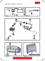
Fig.3-5 

Connect the extention cable 

Ci 

(if used) with the control panel (using the 

Pi 

socket) and the 

end cable 

Cf

.

  Fix the wiring so that it cannot come into contact with moving parts.

Connecting the valves

Fit the gaskets on the connectors which connect the valves to the end cable 

Cf

.

Fig.3


Fix all connectors to the relevant valves, following instructions given on picture 3

, and as ap-

propriate to the type of switch box:

P

Re

gulator valve

2

Electric section valve

 2

G

Main control valve


3

Electric section valve

 3

1

Electric section valve

 1

4

Electric section valve

 4

Use & Instruction Manual

ENG

P00801034_R00.indd   4

23/04/2007   10.02.34

Summary of Contents for GEOline 8406024

Page 1: ...letto il manuale istruzioni Warning do not use the control panel before having read the instruction manual FRA BITIER DE COMMANDE ELECTRIQUE MANUEL INSTRUCTIONS Attention ne pas utiliser le boitier de commande avant d avoir lu le manuel d instructions by Tecomec S p A S MAN RD P N 8406024 2V S MAN RD P N 8406026 2V RP G S MAN RD P N 8406027 4V RP G P00801034_R00 indd 1 23 04 2007 10 02 34 ...

Page 2: ...azione senza l autorizzazione del costruttore Tecomec S p A Il manuale d istruzione è parte integrante della scatola di comando e deve essere conservato in un luogo protetto che ne permetta la pronta consultazione in caso di necessità Il presente manuale diventa parte integrante anche della documentazione dell apparecchiatura su cui è installata la scatola di comando CARATTERISTICHE TECNICHE E DI ...

Page 3: ...nterruttore SG Apre e chiude la valvola di scarico Leva in alto chiude Leva in basso apre Interruttore S1 S4 Apre e chiude la relativa elettrovalvola Leva in alto apre Leva in basso chiude RD Abbassando la leva dell interruttore SG le valvole di sezione vengono automaticamente chiuse anche se i rispettivi deviatori sono in posizione ON Da utilizzare con gruppi di comando con valvola di scarico dem...

Page 4: ...e authorisation of the manufacturer Tecomec S p A is forbidden The instruction manual forms an integral part of the control panel and must be kept in a safe place which enables it to be consulted promptly whenever needed This manual also becomes an integral part of the documentation of the equipment on which the control panel is installed TECHNICAL FEATURES AND PERFORMANCE Description Data Power s...

Page 5: ...trol switch for unloading control valve Switch up for setting OFF switch down for setting ON Switch S1 S4 ON OFF switch for electrovalves Switch up for setting ON switch down for setting OFF RD When the lever of switch SG is lowered the section valves are automatically closed even if their respective switches are in ON position For use with controI units with dump valve DISMANTLING AND DISPOSAL Di...

Page 6: ...bricant Tecomec S p A Le manuel d instruction fait partie intégrante du boitier de commande il doit toujours être conservé dans un lieu protégé mais permettant toutefois son immédiate consultation chaque fois que cela est nécessaire De même le présent manuel fait automatiquement partie intégrante de la documentation de tout appareil sur lequel le boitier de commande est montée CARACTERISTIQUES TEC...

Page 7: ... Levier en haut vanne serrée Levier en bas vanne ouverte Interrupteur S1 S4 Il ouvre et serre l électrovannne correspondante Levier en haut vanne ouverte Levier en bas vanne serrée RD L abaissement du levierde l interrupteur SG ferme automatiquement les vannes de section méme si leurs commutateurs respectifs sont sur ON Elle doit ètre employée sur des groupes de commande équipés d une vanne de déc...

Page 8: ...TIONS G 4 3 2 1 P Ci Cf Fig 3 Ca S1 SP SG Fig 4 Fusibile Fuse Fusible Fig 5 E S U F A 0 1 4 5 5 1 D E R K C A L B Fig 2 E S U F A 0 1 4 5 5 1 D E R K C A L B Y R E T T A B V 2 1 E L E R Fig 1 P00801034_R00 indd 8 23 04 2007 10 02 36 ...

Page 9: ...e Cable intermédiaire Cavo di completamento End cables Cables de integration Part No Type L C00900024 2V RP G 3 m 10 feet C00900025 2V RP G 5 m 16 5 feet C00900026 4V RP G 3 m 10 feet C00900027 4V RP G 5 m 16 5 feet Fig 7 CAVI DI COMPLETAMENTO COMPLETETION CABLES CABLES DE COMPLETEMENT RICAMBI SPARE PARTS PIECES DETACHEE Fig 6 F00600001 3A F00600002 5A F00600003 10A F00600004 15A P00801034_R00 ind...

Page 10: ...P00801034_R00 indd 10 23 04 2007 10 02 36 ...

Page 11: ...P00801034_R00 indd 11 23 04 2007 10 02 36 ...

Page 12: ... 42011 Bagnolo in Piano RE Tel 39 0522 959001 Fax 39 0522 953033 959060 Shipping Dept Via Tasso 2 42023 Cadelbosco Sopra RE Italy www geoline it www tecomec com sales_dept geoline it M e m b e r o f Y a m a G r o u p P00801034_R00 indd 12 23 04 2007 10 02 36 ...

Reviews: