background image

Page | 3


EZ GO


STEP 4.  Install 

BRAKeasy 

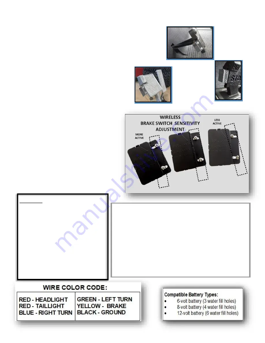
Wireless brake 

light switch 


The patented 

BRAKeasy 

Wireless braking 

sensor combines sensor, mechanical actions 
and wireless technology. Switch automati-
cally adjusts in relation to the speed of the 
cart.  The light is programed to stay on for 
approximately 10 seconds when activated.


Remote Brake Switch Installation:


• 

Install battery as per instructions page 2.


• 

Attach to Left side of brake pedal.  Logo 
must be facing left, right side up. 


• 

Attach as high as possible on the LEFT 
side of the lower section of a divided 
brake pedal.


• 

Carefully mark and drill 

1/16” 

starter 

holes.  


• 

Or after thoroughly cleaning sur-

face, very lightly attach SWITCH with 

double faced tape.  Switch may have 

to be adjusted.  Once sure of location 

press SWITCH firmly in place.


• 

Over tightening screws can fracture plas-

tic –


BE CAREFUL. 


• 

Use elongated holes to adjust , if neces-

sary. See Photo >>>>>>>>>>>>>>>>>>>>


PRECEDENT


YAMAHA


CART BATTERY LIFE 

-

 BEST PRACTICES:


• 

Avoid discharging cart batteries below 40%


• 

Check and fill with distilled water monthly 


• 

Keep batteries clean


• 

Disconnect controller if off charger for 14 days or 

more.


Equalize batteries monthly This process brings low batteries 
up to full charge improving battery performance. 


STEP 1. Following a completed charging cycle  


STEP 2. Unplug charger from cart then plug

-

in again


STEP 3. Let charger complete another charging cycle


Optional 


MOTION ONLY BRAKE LIGHT 

SENSOR INSTALLATION


Attach the brake light sensor to a sur-
face on the same plane as brake pedal 
left side surface. Example, the right 
inside of the golf cart dash storage 
box.  Test by driving the cart and ap-
plying the brakes.  Adjust sensitivity 
as necessary.  Brake light may not ac-
tivate at slow speeds.


Summary of Contents for LiTESeasy Series

Page 1: ... and BLACK ring connector wires to the Controller cable labeled 12 16 volt with a fuse and voltage meter attached RED to RED BLACK to BLACK 3 Attach the ring connectors RED wire to the A POS post and BLACK wire to the B NEG post as shown Depending on the voltage of batteries used voltage me ter should now read about 12 volts or 16 volts A few days after the light kit has been installed disconnect ...

Page 2: ...te buttons too quickly may not activate the lights Buttons work best when held down briefly PRESS BUTTONS LONGER NOT HARDER Pressing too hard can break the buttons HTTPS store tecscan com For Videos and Infor mation about Installing Lights Kits and More MUST PROGRAM BRAKeasy BRAKE SENSOR 1 Insert coin battery into round black plastic frame plus sign up as pictured 2 Slide frame with battery into P...

Page 3: ...press SWITCH firmly in place Over tightening screws can fracture plas tic BE CAREFUL Use elongated holes to adjust if neces sary See Photo PRECEDENT YAMAHA CART BATTERY LIFE BEST PRACTICES Avoid discharging cart batteries below 40 Check and fill with distilled water monthly Keep batteries clean Disconnect controller if off charger for 14 days or more Equalize batteries monthly This process brings ...

Page 4: ...te Trouble Shooting Controller A Press either remote turn signal arrow button B Controller sound present NO C Check with meter for 12 16 volts input NO D Check power in wires The BLACK NO FUSE wire must be on a NEG battery post and the RED FUSED wire on a POS battery post E Check for dead cart batteries F Check the battery posts and wire termi nals for loose connections and or corrosion G Check fu...

Reviews: