background image

P. 3

 | Tecshow Navigator Split 8

English version

2. WARNING

For your own safety, please read this 

user manual carefully before your ini-

tial start-up! 

Unpacking Instructions  

Immediately upon receiving this product, careful

-

ly unpack the carton and check the contents to 

ensure that all parts are present, and have been 

received in good condition. Notify the dealer imme

-

diately and retain packing material for inspection 

if any parts appear damaged from shipping or the 

carton itself shows signs of mishandling. Save the 

carton and all packing materials. In the event that a 

fixture must be returned to the factory, it is im

-

portant that the fixture be returned in the original 

factory box and packing.

Your shipment includes:

• 

Navigator Split 8 with IEC powercable 1,5m 

• 

User manual

LED Expected Lifespan

LEDs gradually decline in brightness over time. 

HEAT is the dominant factor that leads to the accel

-

eration of this decline. Packaged in clusters, LEDs 

exhibit higher operating temperatures than in ideal 

or singular optimum conditions. For this reason 

when all color LEDs are used at their fullest inten

-

sity, life of the LEDs is significantly reduced. It is 

estimated that a viable lifespan of 40,000 to 50,000 

hours will be achieved under normal operational 

conditions. If improving on this lifespan expectancy 

is of a higher priority, place care in providing for 

lower operational temperatures. This may include 

climatic-environmental and the reduction of overall 

projection intensity.

Keep this device away from rain and 

moisture! indoor use only!

Safety Instructions

Every person involved with the installation, opera

-

tion and maintenance of this device has to: 

• 

be qualified 

• 

follow the instructions of this manual

Be careful with your operations. With 

a dangerous voltage you can suffer a 

dangerous electric shock when touch-

ing the wires!

Before your initial start-up, please make sure that 

there is no damage caused by transportation. 

Should there be any, consult your dealer and do not 

use the device. 

To maintain perfect condition and to ensure a safe 

operation, it is absolutely necessary for the user to 

follow the safety instructions and warning notes 

written in this manual. 

Please consider that damages caused by manu

-

al modifications to the device are not subject to 

warranty. This device contains no user-serviceable 

parts. Refer servicing to qualified technicians only. 

Important

The manufacturer will not accept liability for any 

resulting damages caused by the nonobservance 

of this manual or any unauthorized modification to 

the device. 

• 

Never let the power-cord come into contact 

with other cables! Handle the power-cord and 

all connections with the mains with particular 

caution! 

• 

Never remove warning or informative labels 

from the unit. 

• 

Never use anything to cover the ground contact. 

• 

Never look directly into the light source.

• 

Never leave any cables lying around. 

• 

Never use the device during thunderstorms, 

unplug the device immediately. 

Summary of Contents for NAVIGATOR SPLIT 8

Page 1: ...P 1 Tecshow Navigator Split 8 NAVIGATOR SPLIT 8 8 way DMX splitter USER MANUAL MANUAL DE USUARIO PLEASE READ THE INSTRUCTIONS CAREFULLY BEFORE USE POR FAVOR LEA LAS INSTRUCCIÓNES ANTES DE USAR ...

Page 2: ... outputs XLR 3 and XLR 5 apart from its 8 optically isolated outputs with XLR 3 DMX connectors Specifications Features DMX 512 signal Optical isolation DMX signal indicator for input and each of the 8 outputs Optimized signal quality for extended range transmissions Electrical isolation between inputs and outputs Connectors 8 XLR 3 DMX outputs 1 XLR 3 DMX input 1 XLR 5 DMX input 1 XLR 3 DMX thru o...

Page 3: ...rational temperatures This may include climatic environmental and the reduction of overall projection intensity Keep this device away from rain and moisture indoor use only Safety Instructions Every person involved with the installation opera tion and maintenance of this device has to be qualified follow the instructions of this manual Be careful with your operations With a dangerous voltage you c...

Page 4: ... must never be strained There must always be sufficient cable to the device Otherwise the cable may be damaged which may lead to deadly electrical shocks If the external cable is damaged it has to be replaced by a qualified technician If the lens is obviously damaged it has to be replaced So that its functions are not impaired due to cracks or deep scratches If device is dropped or struck disconne...

Page 5: ...ways be secured with a safety attachment e g an appropriate safety net or safety cable When rigging derigging or servicing the de vice always make sure that the area below the installation place is blocked and staying in the area is forbidden Improper installation can cause serious damage to people and property Connection with the mains Connect the device to the mains with the pow er plug Always p...

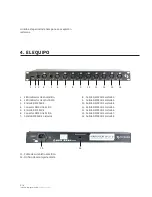
Page 6: ...12 DMX Isolated Output 6 3 pin 13 DMX Isolated Output 7 3 pin 14 DMX Isolated Output 8 3 pin 15 Powercable 16 13mm mounting location plaints against us must be made known in writing or by fax within 10 working days after receipt of the invoice After this period complaints will not be han dled anymore Complaints will only then be consid ered if the client has so far complied with all parts of the a...

Page 7: ...n 230V power or vice versa Remove all packing materials from the Navigator Split 8 Check that all foam and plastic padding is removed You will need a serial data link to run light shows of one or more fixtures using a DMX 512 control ler or to run synchronized shows on two or more fixtures set to a master slave operating mode The combined number of channels required by all the fixtures on a serial...

Page 8: ... 2 Signal Pin 3 Signal 3 Pins canon plug Pin 1 GND screen Pin 2 Signal Pin 3 Signal socket to the first Navigator Split 8 in socket Connect another DMX signal cable from the first Navigator Split 8 DMX out socket to the first unit s in socket Repeat this process to link the second third and fourth units 5 Supply electric power Plug electric mains power cords into each unit s IEC socket then plug t...

Page 9: ...rol ler If there is no data received at the DMX input the problem may be The XLR cable from the controller is not con nected with the input of the first fixture The controller is switched off or defective the cable or connector is detective or the signal wires are swapped in the input connector Note It s necessary to insert a XLR termination plug with 120 Ohm in the last fixture in order to ensure...

Page 10: ...splitter may result in deterioration of the digital DMX signal Maximum recommended DMX data link distance 100 meters Maximum recommended number of movingheads on a single DMX data link 32 fixtures Data Cabling To link fixtures together you must obtain data cables You can purchase DAP Audio certified DMX cables directly from a dealer distributor or con struct your own cable If you choose to create ...

Page 11: ...damages or material fatigue Replacing a Fuse Power surges short circuit or inappropriate elec trical power supply may cause a fuse to burn out If the fuse burns out the product will not function whatsoever If this happens follow the directions below to do so 1 Unplug the unit from electric power source 2 Insert a flat head screwdriver into a slot in the fuse cover Turn the screwdriver to the left ...

Page 12: ... has no power Check the mains power supply Check the fuse internal and or external Fixture is not responding Check the DMX settings for correct addressing Check all connected DMX cables Check the polarity switch settings Fixture is on but there is no sound controlled move ment Make sure you have the correct audio mode on the control switches If audio provided via jack make sure a live audio signal...

Page 13: ...output The bounce mirror motor may have shifted during shipping readjust it accordingly No light output Install a new bulb Fixture is too hot Allow fixture to cool Clean fan Make sure air vents at control panel and front lens are not blocked Turn up the air conditioning The power supply settings do not match local AC voltage and frequen cy Disconnect fixture Check settings and correct if necessary...

Page 14: ...camente aisladas que tienen conectores DMX de 3 pines Especificaciones Características Señal DMX 512 Aislamiento óptico Indicador de señal DMX de entrada y en cada una de las 8 salidas Calidad de señal optimizada durante transmi siones de larga duración Aislamiento eléctrico entre entradas y salidas Conexiones 8 conectores XLR de 3 pines Salida DMX 1 conector XLR de 3 pines Entrada DMX 1 conector ...

Page 15: ...dio se recomienda emplear tempe raturas de funcionamiento menores lo cual puede verse relacionado con las condiciones ambientales climáticas y la reducción de la intensidad total de proyección Proteja el equipo de la lluvia y la hu medad excesiva Este equipo se diseñó para uso en interiores Instrucciones de seguridad Toda persona involucrada con la instalación ope ración y mantenimiento de este di...

Page 16: ...a presión sobre las clavijas del enchufe Procure que siempre haya suficiente cable para el producto De lo contrario el cable puede sufrir daños severos En caso de que el cable de suministro eléctrico se encuentre cortado o dañado póngase en contacto con un técnico para que lo reemplace Sustituya el lente en caso de que se encuentre rayado o dañado para garantizar la óptima salida de luz No utilice...

Page 17: ...vite la circulación de personas debajo del lugar de fijación durante la colocación el des montaje o el mantenimiento del equipo Una instalación incorrecta puede provocar lesiones corporales en las personas y también daños en la propiedad Conexiones Utilice el cable proporcionado para conectar la unidad al suministro eléctrico Verifique que el cable esté conectado en el lugar correcto de acuerdo co...

Page 18: ... DMX XLR 3 aislada 1 8 Salida DMX XLR 3 aislada 2 9 Salida DMX XLR 3 aislada 3 10 Salida DMX XLR 3 aislada 4 11 Salida DMX XLR 3 aislada 5 12 Salida DMX XLR 3 aislada 6 13 Salida DMX XLR 3 aislada 7 14 Salida DMX XLR 3 aislada 8 15 Cable de suministro eléctrico 16 Orificio de montaje de 13mm currido este periodo de tiempo no se aceptarán reclamos 15 16 1 2 3 4 5 6 7 8 9 10 11 12 13 14 Versión Espa...

Page 19: ... de una conexión de datos en serie para armar shows de luces y efectos con uno o más equipos que utilicen un controlador DMX o para ejecutar shows sincronizados en dos o más equipos enlazados en modo maestro esclavo El número total de canales requeridos por todas las unidades enlazadas determina el número de uni dades que el enlace de datos puede sostener Conexión DMX 1 Coloque las unidades en el ...

Page 20: ...l positiva Conecte un extremo de un cable DMX en la salida DMX del controlador y el otro extremo en la entrada DMX del Navigator Split 8 Utilice otro cable DMX para conectar un extremo en la primera salida DMX del Navigator Split 8 y el otro extremo en la entrada DMX de la primera unidad Repita este último paso para enlazar todas las unidades necesarias 5 Conexión al suministro eléctrico Conecte u...

Page 21: ...rolador Si la entrada DMX no recibe señal esto puede deberse a lo siguiente El cable XLR del controlador no está conectado a la entrada de la primera unidad El controlador está apagado o dañado El cable o conector están dañados o se conectaron de forma incorrecta los cables de señal Observación Procure colocar un terminador de 120 Ohm en la última unidad de la cadena para garantizar la transmisión...

Page 22: ... EIA 485 un enlace de datos no puede superar las 30 unidades interconectadas Superar esta cifra sin el uso de un divisor DMX aislado ópticamente puede perjudi car la señal digital transmitida Distancia máxima recomendada para enlaces de datos DMX 100 me tros Número máximo recomendado de proyec tores enlazados 30 unidades Cables de datos Asegúrese de contar con cables de datos para enlazar las unid...

Page 23: ...ben estar dañados o cortados Sustitución del fusible Los picos de tensión los cortocircuitos o un ran go de voltaje inadecuado pueden causar que se queme el fusible Para reemplazarla siga los pasos a continuación 1 Desconecte la unidad del suministro eléctrico 2 Coloque un destornillador plano en una de las ranuras de la cubierta del fusible y gírelo hacia la izquierda mientras hace presión El fus...

Page 24: ...a unidad se paga automáticamente Verifique el interruptor térmico La salida de luz es muy tenue o no ilumina Limpie las piezas ópticas o sustituya la lámpara Revise el switch 220 V El fusible se quema Verifique la carga total aplicada en la unidad El Chase es muy lento Revise la sección de velocidad de movimiento en el manual La unidad no enciende Verifique el suministro eléctrico Revise el fusibl...

Page 25: ... switch 220 V No funciona el flash Reacomode el foco Puede haberse movido durante el envío No hay salida de láser Reacomode el espejo Puede haberse movido durante el envío No hay salida de luz Sustituya la lámpara Permita que la unidad se enfríe Limpie el ventilador Compruebe que no estén obstruidas las ranuras de ventilación Encienda el aire acondicionado Verifique el rango de voltaje de entrada ...

Page 26: ...P 26 Tecshow Navigator Split 8 FOR MORE INFO ON THIS PRODUCT PLEASE CHECK WWW TEC SHOW COM PARA MAS INFORMACION SOBRE ESTE PRODUCTO VISITE WWW TEC SHOW COM Versión Español ...

Reviews: