13
FO 935 ETH
CFO 521 CONCENTRATOR OPERATION
1)
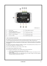
FO IN Input
5)
Dip-switches (not used)
2)
FO OUT output not used
(provision for future developments)
6)
CH3 fibre optic input
3)
CH4 2/3-wires Pt100 input
7)
CH2 fibre optic input
4)
L1-L2-L3 LED
8)
CH1 fibre optic input
2
1
3
4
5
6
7
8
The CFO 521 device electronically acquires and converts the temperatures detected by the FO sensors CH1-CH2-CH3 and
CH4 (Pt100) and sends the detected data to the FO 935 monitoring unit via the TEC digital communication bus.
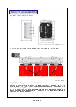
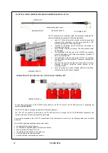
The FO (optical fibre) temperature sensors must be connected to the CH1-CH2-CH3 inputs arranged in the three phases of
the UVW transformer. For a correct interpretation of the measured values it is advisable to combine the CH2 probe with the
central phase V.
The CFO 521 concentrator has a Pt100 input, RTD class A 3-wire probe, for the possible connection of a probe on the core
of the transformer or application of an ambient probe (CH4).
The connection of the Pt100 probe must be 13- White - 14 Red - 15 Red.
The dip-switches setting is always 000 (do not modify)
The LEDs indicate the operating status of the concentrator and of the connected optical fibres.
•
Off LEDs signal the absence of power supply on the CFO 521 device.
•
Single or multiple LED flashing:L1-L2-L3, single flash every 2 seconds, indicates correct functioning of the CH1-
CH2-CH3 channel.
•
Single or multiple flashing LED:L1-L2-L3, double flashing every 2 seconds, indicates the incorrect operation of
the reference channel of the channel CH1-CH2-CH3.
1MN0226 REV.0


