background image

16 

FO 935 ETH


ALARMS AND VENTILATION


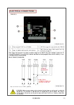
Carry out the electrical connections on the removable terminal blocks only after disconnecting them from the unit. 
When  the  control  unit  is  in  one  of  the  modes  indicated  below  it  does  not  perform  any  thermal  monitoring,  moreover  the 
relays will all be disabled. The fault contact switches and the fault LED flashes. 


Programming viewing display. 


PRG programming. 


Relay test. 


The ALARM and TRIP relays only switch when the set temperature thresholds are exceeded. 
 
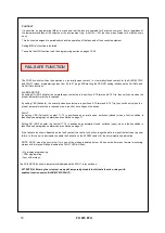
The  FAULT  (fault)  contact,  programmed  in  active  failsafe  mode  (default  YES),  opens  (11-12)  when  the  appliance  is 
powered, only if during the access phase the control unit does not detect anomalies, and keeps the switching until when 
one of the following events occurs: 


Data memory fault (Ech message). 


FO sensor fault (FCC-FOC-FLT) 


CFO 521 concentrator disconnected (TEC) 


Insufficient supply voltage. 


During the power on reset after programming (PRG), displaying of the data (VIS) and relay test. 


The FAULT failsafe mode can be disabled FAULT failsafe "NO" see programming step 30-31 page 20. 


NOTE: in order to avoid unwanted system outages, do not connect the FAULT relay to the transformer tripping circuit. 


FAULT AND RESET MESSAGE SEQUENCE 


Find below the sequence of fault messages and RESET function condition. 


1) ECH         
2) TEC 
3) FO FCC                
4) FO FOC 
5) FO FLT 


The FAN1 and FAN2 contacts can be used to control the cooling fans, or they can be inserted in the conditioning system 
of the transformer room, see paragraph cooling fan control on page 18. 


NOTE: always disconnect the unit before performing any electrical connections. 

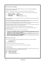
eeprom fault                                       
concentrator communication bus fault 
min. temperature full scale exceeded 
max. temperature full scale exceeded 
broken or disconnected fibre optic sensor 

erasable message 
non-resettable condition           
non-resettable condition 


POWER SUPPLY 

 
The FO 935 ETH can be supplied by 85 to 260 Vac-Vdc, 50/60 Hz irrespectively of polarity in Vdc (terminals 40 - 42). 


This particularity is obtained thanks to the use of a tested power supply, of new conception and realisation, 
which frees the installer from any uncertainty regarding the correct Vac or Vdc power supply. 

The earthing cable must always be connected to terminal 41. 


When the control unit is powered directly by the secondary of the transformer to be protected, it can be burnt out by high 
intensity overvoltages. 
These problems occur if the main switch is closed and the transformer does not have the load (no load test). 
The above is much more evident when the 220 Vac voltage is taken directly from the bars of the secondary 
of the transformer and there is a fixed capacitor battery for power factor correction of the transformer itself. 

If  an  existing  control  unit  must  be  replaced  with  a  new  one,  to  guarantee  its  correct  and  safe  operation,  the 
connecting terminals must be replaced with the new terminals supplied. 


FAULT CONTACT OPERATION (failsafe active) 


FAULT  11-12 NC: ALARM FAULT OR POWER OFF 

FAULT  11-12: NO POWER ON OR NO FAULT 

To protect the control unit against line overvoltages, the PT-73-220 electronic arrester, designed by TECSYSTEM S.r.l. for 
this specific purpose, is recommended. Alternatively, it is advisable to use 110 V AC supply voltages or, even better, 110 
VDC. 


Summary of Contents for FO 935 ETH

Page 1: ...with ISO9001 certified quality system http www tecsystem it R 1 0 12 01 22 Translations of the original instructions ENGLISH TECSYSTEM S r l 20094 Corsico MI Tel 39 024581861 Fax 39 0248600783 FO 935...

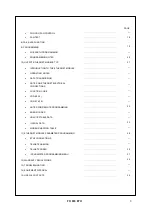
Page 2: ...21 CFO 521 CONCENTRATOR OPERATION 13 6 FO 935 ETH ASSEMBLY 14 7 ELECTRICAL CONNECTIONS 15 FO 935 ETH BACK POWER SUPPLY 16 ALARMS AND VENTILATION FAULT AND RESET MESSAGE SEQUENCE CONC SENSOR DIAGNOSTIC...

Page 3: ...TES DATA TRANSMISSION NOTES ON ETHERNET ELECTRICAL CONNECTIONS FUNCTION CODE CODE 3 10 CODE 16 10 NOTES FOR REMOTE PROGRAMMING 22 ERROR CODES UNACCEPTABLE DATA ILLEGAL DATA 23 MODBUS MAPPING TABLE 11...

Page 4: ...y exceeding 90 and never touch with wet or damp hands If any liquid penetrates the control unit disconnect it immediately and contact technical assistance CLEANING Disconnect the power cable before cl...

Page 5: ...inal 4 pitch poles 3 81 connection CFO 521 Code 2PL0368 Screws tightening torque 0 25Nm CFO 521 Concentrator CFO 521 Concentrator Start guide and QR code 2 Terminals 4 pitch poles 3 81 connection FO 9...

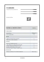
Page 6: ...oards OUTPUTS 2 alarm relays ALARM AND TRIP SPDT 1 relay for faulty probes or operating anomaly FAULT SPST 2 ventilation management relays SPST FAN 1 and FAN 2 Output relays with 10A 250Vca res COS 1...

Page 7: ...s to display temperatures messages and channels 3 LEDs to display the state of the alarms of the selected channel ALARM TRIP FAULT 4 LEDS selection of display mode SCAN AUTO MAN T MAX 2 LEDs to displa...

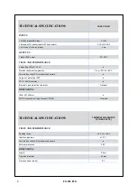
Page 8: ...m 25 C to 60 C Permitted humidity 90 without condensate Degree of protection IP00 PC UL 94 HB container Electronic part protective treatment Optional DIMENSIONS 145x106 7x55mm CONC concentrator fixing...

Page 9: ...ication RS green LED 5 FAULT signalling red LED 16 3 digit channel display 6 FAN 1 yellow LED 17 T max mode selection red LED 7 FAN 2 yellow LED 18 Man mode selection yellow LED 8 Display mode selecti...

Page 10: ...ameters listed in the programming paragraph on pages 19 20 Return the control unit to TECSYSTEM for repairs 3 TEC err this message appears when a loss of communication is detected between the thermome...

Page 11: ...rature of the concentrator ranges from 25 C to 60 C therefore ensure there is adequate space between the concentrator and the transformer Maximum humidity 90 non condensing The CFO 521 support bracket...

Page 12: ...installed apply the protection bracket using the M4 screws supplied FO OPTICAL FIBRE TEMPERATURE SENSOR DIMENSIONS INSTALLATION READING POINT ST CONNECTOR CONNECTION OF THE CONC CFO 521 TO THE FO 935...

Page 13: ...etation of the measured values it is advisable to combine the CH2 probe with the central phase V The CFO 521 concentrator has a Pt100 input RTD class A 3 wire probe for the possible connection of a pr...

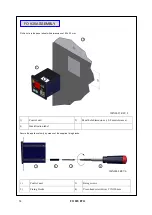
Page 14: ...1 Control unit 2 Panel hole dimensions 0 8 mm tolerance 3 Identification label 1 Control unit 3 Fixing screws 2 Fixing blocks 4 Cross head screwdriver 1X100mm FO 935 ASSEMBLY 1 2 3 4 1MN0008 REV 0 Dr...

Page 15: ...ntrol unit 1MN0257 REV 0 1 2 3 INDICATION AUDIBLE AND VISUAL ALARM CONDITION SYSTEM SHUTDOWN Note image relay contacts in non alarm condition except for the FAULT relay which switches contacts 10 11 c...

Page 16: ...the unit before performing any electrical connections eeprom fault concentrator communication bus fault min temperature full scale exceeded max temperature full scale exceeded broken or disconnected f...

Page 17: ...epairs TEMPERATURE DIAGNOSTICS When one of the sensors detects a temperature higher than 1 C with respect to the pre set value as the alarm limit after approximately 5 seconds the ALARM relay switches...

Page 18: ...5 7 Alarm and 8 10 Trip they switch only when the pre set temperature limits are reached or as a result of no voltage on the device FAULT By setting YES Fail safe contact 11 12 is positioned as norma...

Page 19: ...8 The display shows CH4 Enabling CH4 9 Select YES or NO with YES the CH4 is enabled with NO the CH4 is disabled 10 The ALARM threshold for CH4 appears and the Alarm LED flashes If CH4 NO jump to step...

Page 20: ...y TECSYSTEM might not match your requirements Programming the device is the end user s responsibility The settings of the alarm thresholds and enabling of the functions described in this manual must b...

Page 21: ...hose indicated in the paragraph notes for remote programming The ETH module is always in slave mode The FO 935 ETH control unit is in communication with the network only when it is in temperature read...

Page 22: ...and loads the new settings The information RELAY STATUS indicates the state of excitation of the coils of the relays so it will be subject to the commands of FAIL SAFE At the end of the write command...

Page 23: ...see table SYSTEM Setting and Status Value FCD max see table SYSTEM Setting and Status Value 4 20 max see table SYSTEM Setting and Status Voting Value max see table SYSTEM Setting and Status Note If t...

Page 24: ...FREE See Note R 12 00 00 FREE See Note R 13 00 CPU Setting See Notes RW 14 00 CPU Error See Notes R 15 00 Status Relay See Notes R 16 00 00 FREE See Note R 17 00 Address Modbus address 1 255 R 18 00...

Page 25: ...mpl sign 2 compl Ch1 temper 35 C 195 C R 26 2 compl sign 2 compl Ch1 max temperat 0 C 195 C R 27 2 compl sign 2 compl Ch1 temper alarm set point 1 C 190 C AL RW 28 2 compl sign 2 compl Ch1 temper trip...

Page 26: ...emper 35 C 195 C R 38 2 compl sign 2 compl Ch4 max temperat 0 C 195 C R 39 2 compl sign 2 compl Ch4 temper alarm set point 1 C 190 C AL RW 40 2 compl sign 2 compl Ch4 temper trip set point 1 C 190 C T...

Page 27: ...00 Ch4 Setting See Notes CHx RW 61 00 00 R 62 00 00 R 63 00 00 R 64 00 00 R CHANNELS 1 4 Status Address LO 10 Data HI Data LO Notes 1 Notes 2 W write W write W read write 65 Ch1 story Ch1 status See N...

Page 28: ...ATUS CHn STORY BIT 7 BIT 6 BIT 5 BIT 4 BIT 3 BIT 2 BIT 1 BIT 0 TRIP ALARM FLT FOC FCC RELAY STATUS coil energising status BIT 7 BIT 6 BIT 5 BIT 4 BIT 3 BIT 2 BIT 1 BIT 0 FAULT Relay 1 ON TRIP Relay 1...

Page 29: ...et the Ethernet IP parameters 1 START menu Windows If already enabled the program appears 2 Start the search with the Telnet program Press ENTER to launch the program Entering telnet in SEARCH If inst...

Page 30: ...required 9 START menu Windows 10 Search for the Telnet program 15 Enter 192 168 10 120 9999 16 Press ENTER 12 TELNET SCREEN 11 Press ENTER to launch the program 13 Enter OPEN 14 Press ENTER 17 Enter...

Page 31: ...by the operator 2 Communication parameters between the ETH0 port and the control unit 3 Communication configuration between the ETH0 port and the control unit 4 Communication advanced settings between...

Page 32: ...2 Enter the desired new Gateway IP address press ENTER if you wish to keep the set address press ENTER 4 times At the end of the operation the system will ask if you wish to modify Netmask Type in Y t...

Page 33: ...e 27 4 Enter the new Telnet Password 4 digits max press ENTER if you wish to keep the set password press ENTER Type in S to save the modified data Q to exit Telnet without saving the data Indications...

Page 34: ...om normal domestic waste Returning of used electrical appliances contact TECSYSTEM or the TECSYSTEM agent to receive information on correct disposal of the appliances TECSYSTEM is aware of the impact...

Page 35: ...35 FO 935 ETH TECHNICAL INFORMATION ufficiotecnico tecsystem it COMMERCIAL INFORMATION info tecsystem it USEFUL CONTACTS...

Reviews: