17
FO 935 ETH
FO SENSOR DIAGNOSTICS
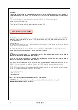
In case of breakage or exceeding of the minimum/maximum full scale value of one of the FO sensors installed on the
machine to be protected, the FAULT relay is instantaneously switched, with the relative sensor failure indication on the
corresponding channel
Display message
FCC:
exceeding of the minimum full scale value
= measured temperature ≤-35°C
Display message
FOC
: exceeding of the maximum full scale value = detected temperature ≥ 195°C
ATTENTION: the FLT indication appears on the display when the concentrator identifies a faulty or disconnected FO
sensor.
To eliminate the message and to restore the Fault switching, check the connections of the FO sensors and replace the faulty
sensor if necessary. In case the minimum/maximum full scale value has been reached, make sure that the environmental
conditions correspond to what is indicated by the control unit.
Note: exceeding of the minimum/maximum full scale can also be caused by possible disturbances on the communication
lines or by strong magnetic fields; in this case, the following is recommended:
Check the correct installation of the sensors and especially of the extension cable between the CFO 521 concentrators and
the FO 935 control unit.
PROGRAMMED DATA DIAGNOSTICS
In case of failure of the internal memory or corruption of programmed data, just after switching on,
Ech
appears with the
relevant Fault contact signal.
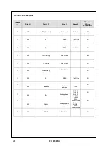
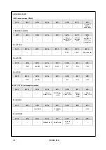
In this case, for safety reasons, the default parameters are loaded automatically (see programming table on pages 19-20).
Eliminate the
Ech
indication by pressing RESET and run programming to enter the desired values.
Finally switch the unit off and back on to check the memory works correctly, if it is damaged
Ech
will be displayed again
(send the control unit to TECSYSTEM srl for repairs).
TEMPERATURE DIAGNOSTICS
When one of the sensors detects a temperature higher than 1°C with respect to the pre-set value as the alarm limit, after
approximately 5 seconds the
ALARM
relay switches and the channel
ALARM
LED (CH
n
)switches on.
When the trip temperature limit is exceeded, after approximately 5 seconds the
TRIP
relay switches and the channel
TRIP
LED (CH
n
) switches on.
As soon as the recorded temperature returns to values equal to or lower than the limit set for the
ALARM
and
TRIP
relays
switching, these relays de-energise and the corresponding LEDs switch off.
The values of
ALARM
and
TRIP
are kept in the internal memories: they can be recalled by entering the Vis modes
(displaying programmed parameters) and modifiable in the PRG mode (programming).
COOLING FAN CONTROL
The FO 935 control unit is fitted with two FAN contacts (FAN1 and FAN2) and, if programmed correctly, can control the fans
switching ON and OFF to cool the transformer.
The FAN1 and FAN2 contacts can manage cooling the transformer and the room where it is installed.
By connecting FAN1 to the tangential ventilation system (the two bars located on the transformer) and FAN2 to the
extractor
will improve the air flow in the cabin; furthermore, the cabin temperature will no longer need to be managed by a thermostat
that is external to the system.
The fans can be controlled in two different ways:
•
Using the temperatures sensed by the sensors on the three columns
CHF
1.2.3 (e.g. ON at 70°C - OFF at 60°C)
•
Through an additional sensor (
CH4/YES
) dedicated to the ambient temperature inside the transformer room.
CHF
4 (e.g. ON at 40°C - OFF at 30°C)
The ON and OFF values are programmable according to the device range. The FAN ON must always be at least 1°C higher
than FAN OFF (recommended ΔT FAN 10°C).
The FAN 1/ 2 LED lights up when the temperature exceeds 1°C the FAN ON threshold, the corresponding relay switches,
and turns off when the temperature goes below 1°C the FAN OFF threshold, the corresponding relay switches.

