A LOOK AT SERVICE SAFETY
Compressor Motor and Component Information
17
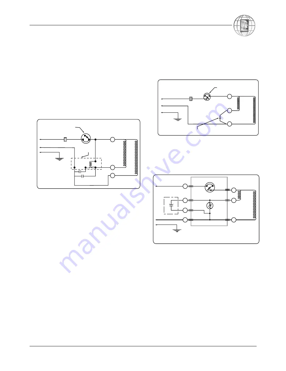
C. Capacitor Start and Run (CSR)
This motor arrangement uses a start capacitor and a
run capacitor in parallel with each other and in
series with the motor start winding. This motor has
high starting torque, runs efficiently, and is used on
many refrigeration and air conditioning applications
through 5 HP. A potential relay removes the start
capacitor from the circuit after the motor is up to
speed. This motor may use either:
•
an external thermal protector, or
•
an internal thermal protector.
D. Permanent Split Capacitor (PSC)
Here a run capacitor is in series with the start wind-
ing. Both run capacitor and start winding remain in
the circuit during start and after motor is up to
speed. This normal starting torque motor is suffi-
cient for capillary and other self-equalizing systems.
No start capacitor or relay is necessary. For addi-
tional starting torque, a proper start assist kit may be
added (see Figure 3-6). Some start assist kits may
include:
•
a wired-in Positive Temperature Coefficient
(PTC) relay, or
•
a module Positive Temperature Coefficient
(PTC) relay.
This motor may use either:
•
an external thermal protector, or
•
an internal thermal protector.
PSC motors are basically air conditioning compres-
sor motors and are very common up through 5 HP.
Figure 3-4.
CSR motor diagram.
Relay -
Potential
Compressor -
Unit Ground
Line 1
Line 2
Ground
Star
t
Winding
Main
Winding
Control
External or Internal
Thermal Protector
C
S
R
Figure 3-5.
PSC motor diagram.
Compressor -
Unit Ground
External or Internal
Thermal Protector
Run Capacitor
Line 1
Line 2
Ground
Star
t
Winding
Main
W
inding
Control
C
S
R
Figure 3-6.
PSC motor diagram with start assist kit
that includes a module PTC relay.
Line 1
Line 2
Ground
Compressor -
Unit Ground
PTC
Relay
Plug-In
Run Capacitor
PTC Starting and
Protector Package
Thermal Protector
Star
t
Winding
Main
Winding
C
C
C
2
C
1
N
S
R


