background image

9

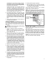
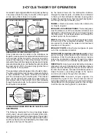
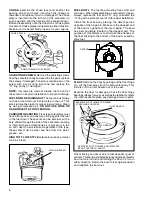
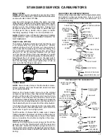
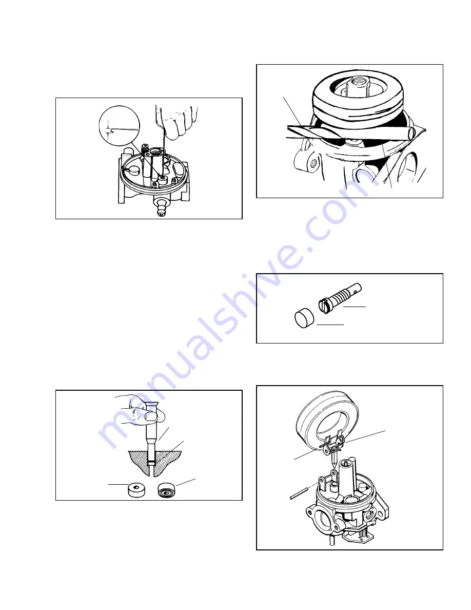
INLET NEEDLE AND SEAT (FLOAT CARBURETORS).

Tecumseh carburetors are built with removable seats

made out of a material called VITON

®

. These seats

are easily removed by bending the end of a paper

clip or wire with a 3/32" hook or use a #4 crochet

hook. Push the hook through the hole in the center

of the seat and remove it. Never reuse the old seat,

always replace it with a new seat.

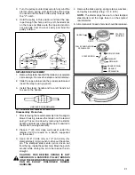
To install a new seat, make sure the seat cavity is

clean, then moisten the seat with a drop of oil to help

it slide into place. Position the seat with the grooved

side of the seal down and carefully push the seat

into its cavity with a 5/32" flat punch until it bottoms

out.

NEEDLE AND SEAT POP-OFF TEST

To test the pop-off pressure, remove the carburetor

from the engine. Be sure to drain any fuel into an

approved container.  Invert the carburetor and remove

the float bowl. Place a drop of an oil based product

such as WD-40 on the tip of the needle valve. Using

a commercially available 0-30 psi pump and gauge,

attach the pumps hose to the carburetor inlet. Apply

approximately 6 psi or until the needle pops off the

seat. The needle should seat at 1.5 psi or greater for

a minimum of 5 minutes. If the minimum 1.5 psi cannot

be maintained for this period of time, then service to

the needle and seat is required.

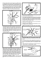
HOOK END

3/32"

DRIVE IN UNTIL

SEAT RESTS ON

BODY SHOULDER

INSERT THIS

FACE FIRST

INLET NEEDLE

SEATS AT THIS

POINT

5/32" FLAT PUNCH

SEAT

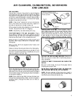
FLOAT HEIGHT SETTINGS

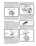
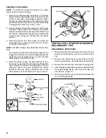
Previously the float height was set by using a 670253A

float setting tool. The new float setting will require an

11/64" drill bit. The procedure for setting the float height

is as follows. Remove the bowl gasket, then hold the

carburetor in the inverted position. Place the drill bit

across the carburetor body opposite and parallel to

the float hinge pin. Adjust the float height by bending

the tab on the float until it touches the bit.

If the required adjustment is minor, the tab adjustment

may be made without removing float and carefully inserting

a small bladed screwdriver to bend the tab. Be careful

not to damage other parts.

RIM

11/64" DRILL BIT

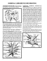
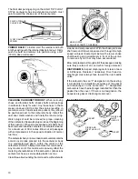
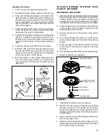
The inlet needle hooks onto the float tab by means of

a spring clip. To prevent binding, the long, straight,

open end of the clip must face the choke end of the

carburetor as shown.

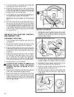
IDLE RESTRICTOR

CAP

THROTTLE END

CHOKE END

LONG END

OF CLIP

CLIP

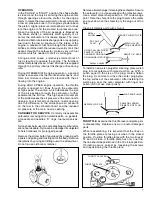
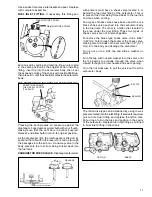
The idle on the Series 8 is metered using a threaded

restrictor (See illustration). Proper torque of this restrictor

is critical, it should be torqued to 5-8 in. lbs. or .5 to

1 nm, or it may vibrate loose. When the restrictor is

placed in the idle circuit passage it is capped with a

tamper resistant plastic cap. If the jet is removed for

cleaning it must be recapped to prevent tampering

when it is re-installed.

Summary of Contents for AH520 -

Page 1: ...t AH520 AH600 AV520 AV600 HSK600 TVS600 This manual covered many engines under an Old form of Identification which will need to be reviewed as well TYPE SPECIFICATION NUMBER 638 670 1398 1642 and Craf...

Page 2: ...29 CONTROL CABLE 30 Page Page GENERAL INFORMATION 1 ENGINE IDENTIFICATION 1 INTERPRETATION OF MODEL NUMBER 1 ENGINE CARE 2 SHORT BLOCKS 2 STORAGE 2 TUNE UP PROCEDURE 3 EXHAUST PORT CLEANING 3 2 CYCLE...

Page 3: ...ulations As a technician it is unlawful to modify or cause a change in the original calibration of these engines All speed adjustments must remain within the limits that are specified for each engine...

Page 4: ...AL NUMBER YEAR 219th DAY 1976 or Aug 6th 1401J TECUMSEH 6219 TYPE SERIAL NUMBER 670 100 TECUMSEH 62290322 YEAR 229th DAY 1976 or Aug 17th 5 30 75 FUEL REGULAR UNLEADED FUEL OIL MIX 32 1 HSK600 1688S 8...

Page 5: ...and fuel screens SHORT BLOCK IDENTIFICATION TAG SBV 2316 SER 4291 SERIAL NUMBER SBV OR SBH IDENTIFICATION NUMBER Using fuel that is not fresh will cause engines to be hard starting especially in cold...

Page 6: ...ean Reinstall carburetor replacing any worn or damaged governor springs or linkage Make proper governor adjustment Adjustments are found in the manual under governor linkage and adjustment and engine...

Page 7: ...ycle engines are lubricated by a gas oil mix The correct mix ratio of oil and gas combines with air in the venturi and enters the crankcase During engine operation the oil clings to all the internal m...

Page 8: ...ly dry Clean air cleaner housing and cover Dry thoroughly Re oil element by applying generous quantity of oil to all sides Squeeze vigorously to distribute oil and to remove excess oil S A E 30 When r...

Page 9: ...The diaphragm movement overcomes the spring tension on the inlet needle and moves the inlet needle off the seat This permits the fuel to flow through the inlet valve to maintain the correct fuel volu...

Page 10: ...re at the main nozzle opening CARBURETOR SERVICE Carefully disassemble carburetor removing all non metallic parts i e gaskets viton seats and needles O rings fuel pump valves etc Nylon check balls use...

Page 11: ...r cleaner Regardless of the type these vents must be clear and free from dirt paint grease etc HIGH TILT FLOAT STYLE carburetors use an external main air bleed FUEL BOWL The fuel bowl must be free of...

Page 12: ...at is required HOOK END 3 32 DRIVE IN UNTIL SEAT RESTS ON BODY SHOULDER INSERT THIS FACE FIRST INLET NEEDLE SEATS AT THIS POINT 5 32 FLAT PUNCH SEAT FLOAT HEIGHT SETTINGS Previously the float height w...

Page 13: ...ith the retainer tabs pointed out Firmly push the bulb and retainer into position using a 3 4 19mm deep well socket CLEANING CARBURETOR BODY When removing choke and throttle shafts check shafts and be...

Page 14: ...m into the body and damage the carburetor Turn a nut on to a 8 32 tap and slide a washer on after it Turn the tap with nut and washer into the valve until the tap begins to protrude through the valve...

Page 15: ...EVER CHOKE SHUTTER DIAPHRAGM GASKET DIAPHRAGM ATMOSPHERIC VENT HOLE INLET FITTING INLET SEAT GASKET INLET NEEDLE SEAT AND SPRING ASSEMBLY CARBURETOR SERVICE PROCEDURE THROTTLE SHAFT AND LEVER THROTTLE...

Page 16: ...IN JET FIXED IDLE RESTRICTER JET EMISSIONIZED DIAPHRAGM CARBURETION BLUE THREAD LOCK SEALANT APPLIED Loosen screw until it just clears throttle lever then turn screw in 1 turn Place detent reference m...

Page 17: ...D IDLE ADJUST NEEDLE AND SPRING LINK THROTTLE LEVER POST CHOKE ROD ROD STOP SPRING IF CURLED OR FRAYED REPLACE COVER INLET FLAP OUTLET FLAP STRAINER FROM THE 6 O CLOCK POSITION THE ROD WILL TURN ABOUT...

Page 18: ...s location Next turn the screw counterclockwise until the engine start to sputter or drops in R P M remember this location Now turn the screw clockwise until it is halfway between these two locations...

Page 19: ...T CARBURETOR CHECKS 21 Adjust float setting 22 Check float shaft for wear and float for leaks or dents 23 Check seal for fuel drain or bowl gasket 24 Is carburetor operating at excessive angle CHECKS...

Page 20: ...is present Also observe the position of the cut out and or holes in choke shutter Some chokes turn clockwise and some turn counterclockwise note the position of the choke shaft prior to removal from t...

Page 21: ...an engine load is applied and the engine s R P M drop the air velocity also drops allowing the governor spring to pull open the throttle shaft and increase engine speed LINKAGE INSTALLATION The best...

Page 22: ...BRACKET SPRING IDLE RPM ADJUSTMENTS HIGH SPEED RPM ADJUSTMENT THIS HOLE NOT PRESENT ON ALL MODELS SPRING VERTICAL ENGINE VARIABLE SPEED MANUAL CONTROL IDLE RPM ADJUSTMENT THIS HOLE NOT PRESENT ON ALL...

Page 23: ...inspect the starter dog s starter cup retainer springs rope washers and the starter pulley for wear or breakage Use one of the following procedures that applies to your application to disassemble repa...

Page 24: ...using a pliers 3 Install the starter handle and tie a left hand knot to secure the handle ONE PIECE ROPE RETAINER LEFT HAND KNOT ROPE HANDLE STARTER DOG PULLEY AND REWIND SPRING ASSY STARTER HOUSING D...

Page 25: ...in the starter body 4 Wind the starter pulley counterclockwise four or five turns to pre load the recoil spring thread the rope through the starter housing eyelet and tie a temporary knot in the rope...

Page 26: ...embly from the engine blower housing remove the starter handle by first pulling a length of rope out using the handle tying a temporary knot in the exposed rope and either untying the knot in handle o...

Page 27: ...pin no longer than 3 4 19 05 mm through the hole in the strut so it catches in the gear teeth This will keep the capsule in the wound position 5 Slip the sheave out of the bracket CAUTION DO NOT ATTE...

Page 28: ...on the engine REWIND STARTER MOUNTED IN HOUSING DISASSEMBLY PROCEDURE 1 Pull rope out to untie knot in rope and slowly release spring tension 2 Remove E clip brake brake spring starter dog and return...

Page 29: ...PRINGS BRUSHES BRUSH CARD ASSY THRUST WASHER BOLT END CAP RETAINER RING SPRING RETAINER ANTI DRIFT SPRING GEAR FRICTION WASHER ENGAGING NUT DUST COVER The 590556 Electric Starter uses a mounting screw...

Page 30: ...SLOWLY Check for 1 Parasitic load or tight engine 2 Worn brushes or weak brush springs 3 Dirty oily or worn commutator 4 Worn bearings in cap assemblies 5 Defective armature STARTER SPINS ENGINE DOES...

Page 31: ...g used Number 1157 for tail stop light 4416 or 4420 for head lights 2 Corroded terminals 3 Cracked wire insulation 4 Broken wires 5 Broken wires covered by insulation 6 A wire grounding out the system...

Page 32: ...applied This action pulls the brake pad away from the inside edge of the flywheel and opens the ignition kill switch On electric start systems the starter is energized by an ignition switch or a two m...

Page 33: ...e rivets from the back side of brake bracket Use the self tapping screw supplied with the new switch to make threads in the bracket Install the interlock switch onto the brake bracket in the proper po...

Page 34: ...uit CONDENSER The condenser acts as an electrical shock absorber to prevent arcing between the contact points as they open Arcing lowers the voltage at the spark plug as well as burn and pit the conta...

Page 35: ...is transferred to a capacitor where it is stored until it is needed to fire the spark plug The magnet continues rotating past a trigger coil where a low voltage signal is produced and closes an elect...

Page 36: ...cause the ball bearing to dislodge from the shroud base and force the lower thrust face of the crankshaft against the cylinder thrust face TO CORRECT THIS CONDITION RAP SHARPLY WITH RAWHIDE MALLET ON...

Page 37: ...e sure electrical leads are intact especially where they enter the coil Check operation of the coil using an approved tester following the instructions furnished with the test unit If laminations are...

Page 38: ...secure it in place T D C B T D C DIAL SCREW DIAL AT 0 DIAL AT 090 2 29 mm DIAL AT 080 2 0 mm While watching the needle on the dial indicator rotate the crankshaft counterclockwise when looking at the...

Page 39: ...fied by its square configuration which will identify the need for the proper flywheel key or sleeve STEPPED KEY STEPPED END TOWARD ENGINE FLYWHEEL SLEEVE ROUND COIL Timing this system consists of havi...

Page 40: ...de of flywheel set points per specification and set air gap between flywheel magnets and laminations to 005 to 008 Air gap gauge part number 670216 which measures 0075 may be used Use Loctite 242 Blue...

Page 41: ...the friction screw until the lever will not vibrate out of position when the engine is running and yet can be easily rotated when speed is adjusted Adjust ignition points to proper specification Remov...

Page 42: ...cam is adjusted for both positions Now tighten the screws Using a dial indicator set the piston to the specified Before Top Dead Center BTDC dimension OUTBOARD TIMING SOLID STATE Follow these step by...

Page 43: ...he number 2 position of the timing tool Hold this position Adjust the actuating cam to touch the post without moving it Tighten the lock screw to hold the cam in place Recheck to insure that the high...

Page 44: ...heck at various places to make sure that the gap between the ends of the ring do not exceed the dimensions indicated in the Table of Specifications Bore wear can be checked by the same method except u...

Page 45: ...ods have match marks on the connecting rod and cap Make certain these match marks are aligned when assembling NEEDLE BEARINGS Needle bearings may be single or split row Split needles are to be install...

Page 46: ...t and ball bearing heat shroud base to expand bearing seat and drop ball bearing into seat of base shroud Allow to cool On outboards only install shroud base onto cylinder but before tightening screws...

Page 47: ...an ice pick to pry out the retainer spring then remove the retainer and seal In some cases it may be necessary to remove the crankshaft to remove the oil seals OUTBOARD SEAL SERVICE Oil seals on the p...

Page 48: ...udge marks on smooth side If these marks are gone feel for a rough edge and assemble away from sealing surface AUTOMATIC COMPRESSION RELEASE DOUBLE REED TYPE Cranking compression pressures bleed past...

Page 49: ...ours of operation It is recommended that the cylinder head be removed and carbon cleaned from the ports cylinder head and top of piston CAUTION Do Not Scratch Metal Surfaces With the cylinder head rem...

Page 50: ...adjustment Adjust carburetor Loose or defective magneto wiring Check magneto wiring for shorts or grounds repair if necessary Sheared or incorrect flywheel key or adapter sleeve Replace with correct...

Page 51: ...POWER Choke partially closed Open choke Blown head gasket Replace head gasket Improper carburetor adjustment Adjust carburetor Improper or partially sheared flywheel key or Replace with new correct k...

Page 52: ...clogged Open vent hole Crankcase air leak Inspect and replace gasket or seal Governor parts sticking or binding Clean and if necessary repair governor parts Carburetor throttle linkage or throttle sh...

Page 53: ...ical Crankshaft Engines 638 thru 638 100 6 639 thru 639 13A 13 640 02 thru 640 06B 21 640 07 thru 640 21 A 22 640 23 36 641 thru 641 14 11 642 01 A 9A 642 02 A thru G 9A 642 02E F 9B 642 03 A B 9A 642...

Page 54: ...283012 8 200 2131128 31 200 2132228 29 Craftsman Horizontal Crankshaft Engines Craftsman No Column No 200 503111 16 200 583111 16 200 593121 16 200 602112 35 200 613111 16 200 633111 35 200 643121 35...

Page 55: ...64 0655 1 664 0655 1 664 0975 1 664 0655 1 664 0665 1 689 0665 1 689 0665 1 689 0985 1 689 0665 1 689 0645 1 638 0645 1 638 0645 1 638 0955 1 638 0645 1 638 Bot 0655 1 664 0655 1 664 0655 1 664 0965 1...

Page 56: ...955 1 638 0645 1 638 0645 1 638 0645 1 638 0645 1 638 Bot 0965 1 664 0655 1 664 0655 1 664 0655 1 664 0655 1 664 Piston Ring 0925 2 35 0615 1 562 0615 1 562 0615 1 562 0615 1 562 Width 0935 2 375 0625...

Page 57: ...0655 1 664 0665 1 689 0665 1 689 0975 2 477 0985 2 413 0665 1 689 0645 1 638 0645 1 638 0645 1 638 0955 2 426 0645 1 638 Bot 0655 1 664 0655 1 664 0655 1 664 0965 2 451 0655 1 664 Piston Ring 0615 1...

Page 58: ...664 0975 1 664 0655 1 664 0645 1 638 0645 1 638 0665 1 664 0985 1 689 0665 1 664 0655 1 664 0655 1 664 0645 1 638 0955 2 426 0645 1 638 0645 1 638 0645 1 638 Bot 0655 1 664 0965 2 451 0655 1 664 0655...

Page 59: ...55 1 664 0655 1 664 0665 1 689 0665 1 689 0665 1 689 0645 1 638 0645 1 638 0645 1 638 0645 1 638 0645 1 638 Bot 0655 1 664 0655 1 664 0655 1 664 0655 1 664 0655 1 664 Piston Ring 0615 1 562 0615 1 562...

Page 60: ...0655 1 664 0655 1 664 0655 1 664 0655 1 664 0665 1 689 0665 1 689 0665 1 689 0665 1 689 0665 1 689 0645 1 638 0645 1 638 0645 1 638 0645 1 638 0645 1 638 Bot 0655 1 664 0655 1 664 0655 1 664 0655 1 6...

Page 61: ...655 1 664 0655 1 664 0655 1 664 0655 1 664 0665 1 689 0665 1 689 0665 1 689 0665 1 689 0665 1 689 0645 1 638 0645 1 638 0645 1 638 0645 1 638 0645 1 638 Bot 0655 1 664 0655 1 664 0655 1 664 0655 1 664...

Page 62: ...0655 1 664 0655 1 664 0655 1 664 0655 1 664 0665 1 689 0665 1 689 0665 1 689 0665 1 689 0665 1 689 0645 1 638 0645 1 638 0645 1 638 0645 1 638 0645 1 638 Bot 0655 1 664 0655 1 664 0655 1 664 0655 1 66...

Page 63: ...664 0655 1 664 0655 1 664 0655 1 664 0665 1 689 0665 1 689 0665 1 689 0665 1 689 0665 1 689 0645 1 638 0645 1 638 0645 1 638 0645 1 638 0645 1 638 Bot 0655 1 664 0655 1 664 0655 1 664 0655 1 664 0655...

Page 64: ...89 0665 1 689 0665 1 689 0665 1 689 0645 1 638 0655 1 664 0655 1 664 0655 1 664 0655 1 664 0655 1 664 Bot 0655 1 664 0665 1 689 0665 1 689 0665 1 689 0665 1 689 0665 1 689 Piston Ring 0615 1 562 0615...

Page 65: ...7 8 5 Reed Plate Cover Plate 35 45 4 5 Reed Hold down 15 25 1 5 3 Compression Release Cover 30 40 3 5 4 5 Shroud Base to Block 80 100 9 11 Starter Mounting Screws Metal 50 70 5 5 8 Starter Mounting S...

Page 66: ...rdown and reassembly of the 900 series transaxles This video will show a complete step by step procedure for teardown and reassembly of the 900 910 and 920 series transaxles 695185 Electrical Troubles...

Page 67: ...64...
Page 68: ...sed on magneto end of all two cycle engines with one piece oil seals and P T O end of 1600 series Includes tool No 670280 and center screw No 670257 Used on 2 cycle connecting rod screws No 670307 Use...

Reviews: