36
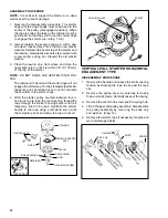
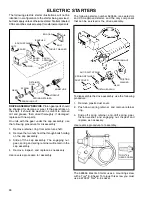
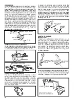
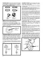
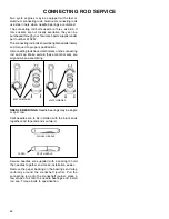
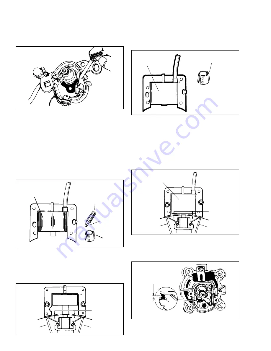
FIXED TIME SYSTEM (External Coil).
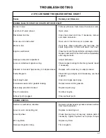
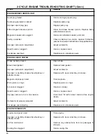
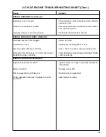
This system
has the contact points and condenser mounted under
the flywheel with the laminations and coil mounted
outside the flywheel. This system is identified by the
square hole in the stator, the round configuration of
the coil, and a stepped flywheel key.
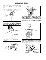
Begin the timing procedure, torque down the stator
bolts to secure the stator in place. Next rotate the
crankshaft until the point arm is resting on the high
side of the ignition cam. Set the point gap at to the
proper specification by loosening the screw on the
movable point, and inserting a feeler gauge between
the contact points. Tighten the screw on the movable
point and then recheck the point gap. Be sure to clean
the contact points with lint free paper.
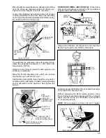
Reinstall the proper flywheel key, flywheel, washer,
and torque down the flywheel nut to specification.
Reinstall the external coil, but do not tighten down
the mounting screws.
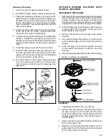
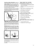
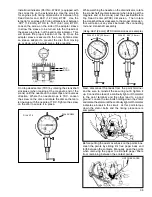
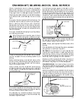
SOLID STATE (CDI).
This is an all electronic ignition
system with the components sealed in a module and
located outside the flywheel.
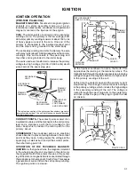
A Solid State module can be identified by its square
configuration, which will identify the need for the proper
flywheel key or sleeve.
STEPPED KEY
STEPPED
END
TOWARD
ENGINE
FLYWHEEL
SLEEVE
ROUND COIL
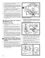
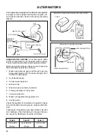
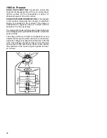
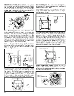
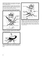
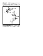
Timing this system consists of having the proper .0125"
(.317 mm) air gap gauge, (Part No. 670297) between
the magnets and laminations and torque down the
mounting screws to specification. Remove air gap
gauge and rotate flywheel to check for any possible
striking points. If none are found, the air gap is set
correctly and the timing procedure is completed.
.0125”
(.317 mm)
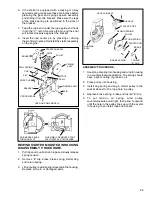
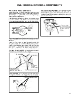
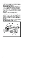
The proper air gap setting between the flywheel magnets
and the laminations on both the fixed time and CDI
systems is .0125'. Place .0125' gauge, part No. 670297
between the magnets and laminations and torque down
mounting screws to specification. Recheck gap setting
to make certain there is proper clearance between
the magnets and laminations.
NOTE:
Due to variations
between pole shoes, air gap may vary from .005/.020'
when flywheel is rotated. There is no further timing
adjustment on external lamination systems.
FLYWHEEL SLEEVE
SQUARE MODULE
SQUARE MODULE
.0125"
SET GAP
PER SPECIFICATION
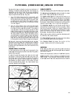
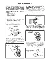
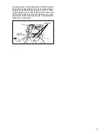
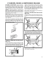
OTHER IGNITION SYSTEMS.
Ignition systems on
engines with a non-adjustable stator, set the points
per specification. If the coil is located under the flywheel,
no other timing is required.
Summary of Contents for AH520 -
Page 67: ...64...

