18
SERVICE HANDBOOK
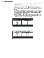
Minimum starting voltage for the compressor when it is attempting to start (locked
rotor) is listed in Table 3-1.
•
Unequalized system pressure:
Head and suction pressures must be equal and not
more than the pressures listed in Table 3-2. Refrigeration metering device (cap tube or
TX valve) should equalize system pressure within 3 minutes. Unequal system pressure
may be caused by excessive refrigerant charge, short cycling thermostat, or system
restriction.
•
Circuit breaker or fuse trips:
Branch circuit fuses or circuit breakers sized too small will
cause nuisance tripping (see “Fuse and Circuit Breaker Sizing” on page 27). If the fuse
or circuit breaker trips, see “Identifying Compressor Electrical Problems” on pages 40-
41 for electrical troubleshooting techniques.
•
Electrical components:
A failed run capacitor will not allow the compressor to start,
and it will trip the thermal protector. See “Identifying Compressor Electrical Problems”
on pages 40-41 for electrical troubleshooting techniques.
Table 3-1: Minimum Starting Voltage
Serial Label Voltage
Min. Voltage for Start
115
103
208
188
230
207
208/230
198
265
239
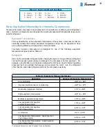
Table 3-2: Maximium Equalized Pressures
Refrigerant
Maximium Equalized Pressures
R-410A
275 psig
R-22
170 psig
R-407C
180 psig
R-134a
104 psig
Pressures are at 90°F Ambient
Summary of Contents for AH5540E
Page 1: ...Hermetic Compressor Service Handbook Wholesale Distribution North America...
Page 2: ......
Page 3: ...Hermetic Compressor Service Handbook Ann Arbor MI 48108 REV 3 11...
Page 4: ......
Page 8: ......
Page 9: ...Chapter 1 General Service Safety Precautions...
Page 16: ......
Page 17: ...Chapter 2 Model and Application...
Page 22: ......
Page 23: ...Chapter 3 Compressor Motor and Component...
Page 36: ......
Page 37: ...Chapter 4 Servicing...
Page 38: ...30 SERVICE HANDBOOK...
Page 79: ...71...
Page 80: ......
Page 81: ...Chapter 5 Installation and Replacement...
Page 96: ......
Page 97: ...Liquid refrigerant migration to compressor FIGURE 6 1 Chapter 6 Operation...
Page 108: ......
Page 109: ...Appendix...
Page 113: ...105 Reciprocating Compressor FIGURE A 2 Internal view of typical air conditioning compressor...
Page 118: ...110 SERVICE HANDBOOK Notes...
Page 119: ......


