22
SERVICE HANDBOOK
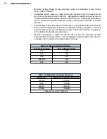
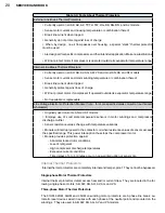
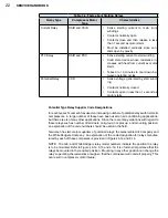
Table 3-4: Facts about Starting Relays
Relay Type
Compressor Motor
Type
Characteristics
Current Relay
RSIR and CSIR
•
Sense starting current to main (run)
windings
•
Contacts normally open
•
Contacts close and then release in less
than 1 second as motor starts
•
Must be installed vertically since con-
tacts open by gravity
PTC Relay
RSIR and PSC
•
Sense starting current to start winding
•
Solid state device whose resistance in-
creases with heat from current as motor
starts
•
Takes 3 to 10 minutes to cool down be-
tween operating cycles
Potential Relay
CSR
•
Sense voltage generated by start wind-
ing
•
Contacts normally closed
•
Contacts open in less than 1 second as
motor starts
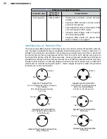
Potential Type Relay Supplier Code Designations
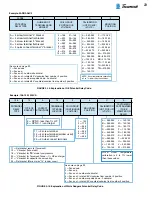
In recent years, Tecumseh has used an increasing number of potential relays with hermetic
compressors. A large number of these have been used on air conditioning applications,
but there are also many other applications. Since there are many variations with regard to
these relays such as number of terminals, coil group, hot pick up, and mounting position,
an explanation of the code numbers should be useful in the field.
Tecumseh has two major suppliers of potential relays: the General Electric Company and
the White Rodgers Company. An explanation of the code designation for relays manufac-
tured by each of these companies is provided in Figures 3-14 and 3-15.
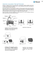
NOTE: The G.E. and White Rodgers relay model numbers indicate the position the relay
is to be mounted. Refer to Figures 3-14, 3-15 and 3-16. It is of utmost importance that the
relays be mounted in the required position. Mounting in any other position can change the
relay’s operating characteristics enough so that the compressor will not start properly. This
can result in compressor motor failure.
Summary of Contents for AH5540E
Page 1: ...Hermetic Compressor Service Handbook Wholesale Distribution North America...
Page 2: ......
Page 3: ...Hermetic Compressor Service Handbook Ann Arbor MI 48108 REV 3 11...
Page 4: ......
Page 8: ......
Page 9: ...Chapter 1 General Service Safety Precautions...
Page 16: ......
Page 17: ...Chapter 2 Model and Application...
Page 22: ......
Page 23: ...Chapter 3 Compressor Motor and Component...
Page 36: ......
Page 37: ...Chapter 4 Servicing...
Page 38: ...30 SERVICE HANDBOOK...
Page 79: ...71...
Page 80: ......
Page 81: ...Chapter 5 Installation and Replacement...
Page 96: ......
Page 97: ...Liquid refrigerant migration to compressor FIGURE 6 1 Chapter 6 Operation...
Page 108: ......
Page 109: ...Appendix...
Page 113: ...105 Reciprocating Compressor FIGURE A 2 Internal view of typical air conditioning compressor...
Page 118: ...110 SERVICE HANDBOOK Notes...
Page 119: ......


