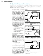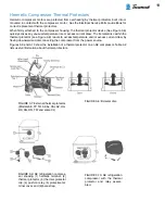
25
Run Capacitors
Since January 1979, capacitors provided by Tecumseh
have contained non-PCB oils or have been constructed
using non-PCB impregnated metallized paper elec-
trodes and polypropylene dielectric. These capacitors
are protected against case rupture by a device within
the capacitor can if failure occurs. The operation of this
safety device could cause the terminal end to bulge
outward ½”. Suitable head space and/or rubber caps
should be provided when installing such capacitors.
In some instances, for reasons of both space and
economics, it is advantageous to use two capacitors
whose MFD values add up to the total amount speci-
fied. In these cases, the capacitors should be connect-
ed in parallel. Rated voltage for each should not be
less than that specified.
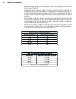
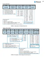
The tolerance on a run capacitor is 10%, and therefore
only one rating figure is given. You should not go be-
low this figure on any application. You may exceed this
figure by a small amount, and the limits are shown in
Table 3-5:
Remember the voltage rating of all capacitors must be the same or greater than the original
rating. If the voltage rating is not known, use 370 volt capacitors on 115 volt units and 440
volt capacitors on 230 volt units. Table 3-6 lists useful information regarding capacitors.
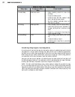
Table 3-6: Facts about Capacitors
Capacitor Type
Compressor
Motor Type
Characteristics
Start Capacitor
CSIR and CSR
•
Designed to operate for only a few seconds
during start
•
Taken out of start winding circuit by relay
•
Excessive start capacitor MFD increases
start winding current, increases start winding
temperature, and may reduce start torque
•
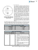
Capacitors in CSR motors should have
15,000 ohm, 2 watt bleed resistor across ter-
minals
•
Capacitor rated voltage must be equal to or
more than that specified
•
Capacitor MFD should not be more than that
specified
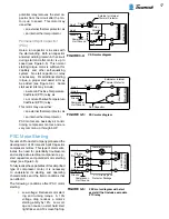
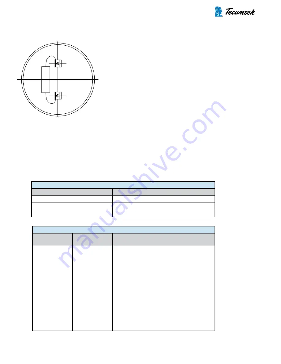
FIGURE 3-18: 15000 OHMS 2 WATT
± 20% bleeder resistor wired across
capacitor terminals.
Table 3-5: Facts about Capacitors continued on next page
Table 3-5: Limits for Run Capacitor Ratings
Specific Rating
Maximum Addition
10 to 20 MFD
+ 2 ½ MFD
20 to 50 MFD
+ 5 MFD
Over 50 MFD
+ 10 MFD
Summary of Contents for AH5540E
Page 1: ...Hermetic Compressor Service Handbook Wholesale Distribution North America...
Page 2: ......
Page 3: ...Hermetic Compressor Service Handbook Ann Arbor MI 48108 REV 3 11...
Page 4: ......
Page 8: ......
Page 9: ...Chapter 1 General Service Safety Precautions...
Page 16: ......
Page 17: ...Chapter 2 Model and Application...
Page 22: ......
Page 23: ...Chapter 3 Compressor Motor and Component...
Page 36: ......
Page 37: ...Chapter 4 Servicing...
Page 38: ...30 SERVICE HANDBOOK...
Page 79: ...71...
Page 80: ......
Page 81: ...Chapter 5 Installation and Replacement...
Page 96: ......
Page 97: ...Liquid refrigerant migration to compressor FIGURE 6 1 Chapter 6 Operation...
Page 108: ......
Page 109: ...Appendix...
Page 113: ...105 Reciprocating Compressor FIGURE A 2 Internal view of typical air conditioning compressor...
Page 118: ...110 SERVICE HANDBOOK Notes...
Page 119: ......

