42
SERVICE HANDBOOK
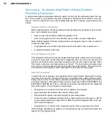
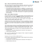
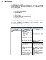
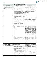
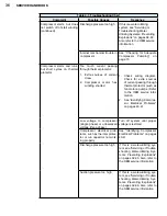
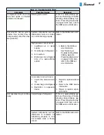
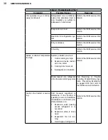
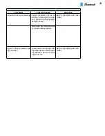
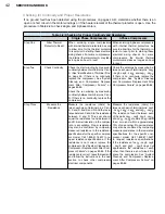
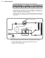
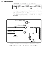
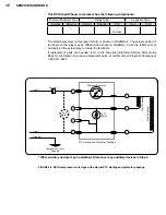
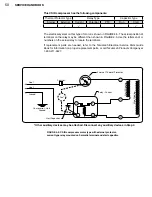
Checking for Continuity and Proper Resistance
If no ground fault has been detected using the procedures on pages 40-41, determine whether there is an
open or short circuit in the motor windings or if the heater element of the thermal protector is open. Use the
procedure in Table 4-2 to check single- and 3-phase motors.
Table 4-2: Checking for Proper Continuity and Resistance
Single Phase Compressors
3-Phase Compressors
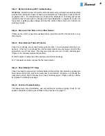
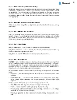
Step One
Allow Thermal
Protector to Reset
When servicing single compressors
with internal thermal protectors, be sure
to allow time for the thermal protector
to reset prior to starting these electrical
wiring checks. For some compressors,
the internal thermal protector may take
as long as an hour to reset
When servicing 3-phase compressors
with internal thermal protectors, be
sure to allow time for the thermal pro-
tector to reset prior to starting these
electrical wiring checks. For some
compressors, the internal thermal
protector may take as long as an hour
to reset
Step Two
Check Continuity
Check the start winding by measuring
continuity between terminal pins C and
S. (See "Identification of Terminal Pins"
on page 26. If there is no continuity,
replace the compressor. See "System
Cleanup and Compressor Replace-
ment After Compressor Failure" on
pages 83-86.
Check the run winding by measuring
continuity between terminal pins C and
R. If there is no continuity, replace the
compressor.
Check the windings by measuring be-
tween each pair of terminal pins: Leg1
- Leg2, Leg2 - Leg3, and Leg1 - Leg3.
If there is no continuity, replace the
compressor. See "System Cleanup
and Compressor Replacement After
Compressor Failure" on pages 83-86.
Step Three
Measure the
Resistance
Measure the resistance (ohms) be-
tween each pair of terminal pins: C and
S, C and R, and S and R. Add the resis-
tance between C and S to the resistance
between C and R. This sum should
equal the resistance found between S
and R. A small deviation in the compar-
ison is acceptable. Proper resistance
may also be confirmed by comparing
measured resistance to the resistance
specifications for the specific compres-
sor model. Call 1-800-211-3427 to re-
quest resistance specifications. If the
resistance is not correct, replace the
compressor. See "System Cleanup and
Compressor Replacement After Com-
pressor Failure" on pages 83-86. If the
resistance is correct, leave the leads off
and follow the instructions in the next
section to check other compressor
electrical components.
Measure the resistance (ohms) be-
tween each pair of terminal pins: Leg1
- Leg2, Leg2 - Leg3, and Leg1 - Leg3.
The resistance found between each
of the pairs Leg1 - Leg2, Leg2 - Leg3,
and Leg1 - Leg3 should all be greater
than zero and within approximately
10% of one another. Proper resistance
may also be confirmed by comparing
measured resistance to the resistance
specifications for the specific com-
pressor model. Call 1-800-211-3427
to request resistance specifications.
If the resistance of Leg1 - Leg2, Leg2
- Leg3, and Leg1 - Leg3 does not
approximate the resistance of each
other, then there is a short circuit. Re-
place the compressor. See "System
Cleanup and Compressor Replace-
ment After Compressor Failure" on
pages 83-86.
Summary of Contents for AH5540E
Page 1: ...Hermetic Compressor Service Handbook Wholesale Distribution North America...
Page 2: ......
Page 3: ...Hermetic Compressor Service Handbook Ann Arbor MI 48108 REV 3 11...
Page 4: ......
Page 8: ......
Page 9: ...Chapter 1 General Service Safety Precautions...
Page 16: ......
Page 17: ...Chapter 2 Model and Application...
Page 22: ......
Page 23: ...Chapter 3 Compressor Motor and Component...
Page 36: ......
Page 37: ...Chapter 4 Servicing...
Page 38: ...30 SERVICE HANDBOOK...
Page 79: ...71...
Page 80: ......
Page 81: ...Chapter 5 Installation and Replacement...
Page 96: ......
Page 97: ...Liquid refrigerant migration to compressor FIGURE 6 1 Chapter 6 Operation...
Page 108: ......
Page 109: ...Appendix...
Page 113: ...105 Reciprocating Compressor FIGURE A 2 Internal view of typical air conditioning compressor...
Page 118: ...110 SERVICE HANDBOOK Notes...
Page 119: ......


