86
SERVICE HANDBOOK
Table 5-8: Suggested Maximum Pressure Drop (psi) for
Temporary Suction Filter-Drier Installation During Cleanup
Application
Air Cond
High
Medium
Low
Evaporator
Range, °F
+55 to +32
+55 to +20
+30 to -10
+10 to -20
-20 to -40
R-12, R-134a
6
6
3
2
3/4
R-22, R-
404A, R-
407C, R-502,
R-507
8
8
4
3
1 1/2
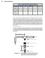
Test for Acidity if Multiple Motor Failures Have Occurred
If the system has suffered multiple motor failures, it is advisable that the oil of the re-
placement be tested and judged acid free before the system is considered satisfactorily
cleaned. An oil sample may be taken from a hermetic system if at the time the replacement
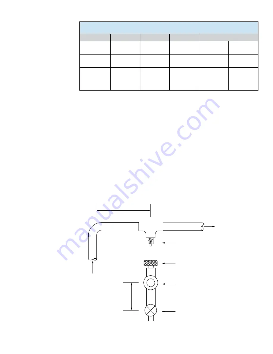
compressor was installed an oil trap is installed in the suction line (see Figure 5-12). When
the trapped oil level appears in the sight glass (less than an ounce is needed) the oil may
be slowly transferred to the beaker of the acid test kit as available from several manufac-
turers. A reading of less than 0.05 acid number is an indication that the system is free of
acid. A reading of higher than 0.05 means continued cleaning is required. Replace liquid
line filter-drier.
Monitor the System
The above procedure for the cleanup of hermetic systems after motor failure through the
use of suction line filter-drier will prove satisfactory in most instances provided the system
is monitored and kept clean by repeated drier changes, if such are needed. The failure to
follow these minimum cleanup recommendations will result in an excessive risk of repeat
motor failure.
Schrader Valve Vertically Downward
Female Schrader Valve Connection
1/2" Liquid Sight Glass
1/2" Shut Off Valve
2" M
inimum
At Least 6 Diameters
Suction Line
Method of obtaining oil sample on hermetic system.
After satisfactory oil test, Schrader valve may be
capped and the oil sample taken to the next job.
FIGURE 5-12:
Summary of Contents for AH5540E
Page 1: ...Hermetic Compressor Service Handbook Wholesale Distribution North America...
Page 2: ......
Page 3: ...Hermetic Compressor Service Handbook Ann Arbor MI 48108 REV 3 11...
Page 4: ......
Page 8: ......
Page 9: ...Chapter 1 General Service Safety Precautions...
Page 16: ......
Page 17: ...Chapter 2 Model and Application...
Page 22: ......
Page 23: ...Chapter 3 Compressor Motor and Component...
Page 36: ......
Page 37: ...Chapter 4 Servicing...
Page 38: ...30 SERVICE HANDBOOK...
Page 79: ...71...
Page 80: ......
Page 81: ...Chapter 5 Installation and Replacement...
Page 96: ......
Page 97: ...Liquid refrigerant migration to compressor FIGURE 6 1 Chapter 6 Operation...
Page 108: ......
Page 109: ...Appendix...
Page 113: ...105 Reciprocating Compressor FIGURE A 2 Internal view of typical air conditioning compressor...
Page 118: ...110 SERVICE HANDBOOK Notes...
Page 119: ......


