background image

4.1

Introduction

The PCD-8006 card provides six 8-bit bidirectional digital ports.

The first three ports (identified as DIO0, DIO1 and DIO2) use the D-Sub 25 connector
located on the card bracket, the other three ports (ie. DIO3, DIO4 and DIO5) use header
type connectors located at the back edge of the card.

In case of the standard format card (ie. PCD-8006), the DIO3 port is accessed on the card
bracket via adapter cable PCE-8019 terminated with D-Sub 9 connector. Remaining two
ports (ie. DIO4 and DIO5) can be accessed via adapter cable PCE-1620 (card bracket with
D-Sub 9 connector), or other types from the PCE-16xx series adapter boards.

Note:

Unlike the adapter cable PCE-8019, the PCE-16xx boards are not included in the
delivery package of the card.

In case of the low-profile format card (ie. PCD-8006/LP) all three ports DIO3, DIO4 and
DIO5 can be accessed via adapter cable PCE-8025/LP (low-profile card bracket with D-Sub
25 connector); there are currently no other option available.

Note:

The PCE-8025/LP adaptor board is not included in the delivery package of the card.

The signal direction of DIO port (ie. input or output option) can be selected independ for
each 8-bit port (it is not possible to select direction individually for each of the eight signals
of one DIO port) from the user software. 

The port direction and output data after computer is turned on or restarted are stored in the
on-board EEPROM memory and can modify by the software utility (by default, all ports are
set as input).

4.2

Description of digital ports

Drivers and receivers based on HCTMOS technology were used for digital ports.

In the output mode (ie. driver mode), the HCTMOS circuits provide true 5 V signal levels
with a high output current with low voltage drop and can therefore be used for direct
control of LEDs, optocouplers, or miniature relays (coil parameters 5 V, 500 Ohm).

In the input mode (ie. receiver mode), the HCTMOS circuits provide not only TTL signal
compatibility, but moreover high input impedance, very low leakage current and
protection diodes. The unconnected state of inputs represents the H logic level generated
by pull-up resistors 10 kOhm against a voltage of 5 V, and the inputs can be therefore also
used to direct connecting of floating contacts.

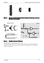
Check the Appendix, Figure 3 for detail information.

Note:

Unfortunately, the concept of bidirectional ports does not provide the overvoltage
protection available to other ports of  PCI/PCIe TEDIA cards.

4.3

Interrupt logic

The PCD-8006 card allows to trigger an interrupt (simultaneously with the timestamp IRQ
generator) by any combination of rising or falling edges of the signals of all digital ports.

4.

Digital Ports

PCD-8006

User Guide

rev. 10.2015

I - 4

Summary of Contents for PCD-8006

Page 1: ...Digital I O PCIe card PCD 8006 User Guide ...

Page 2: ...tions of this document without prior notice to holders of this edition TEDIA provides this document as is without warranty of any kind either expressed or implied including but not limited to its particular purpose TEDIA reserves the right to make improvements and or changes to this manual or to the products and or the programs described in this manual at any time Information provided in this manu...

Page 3: ...igital ports I 2 2 2 Interrupt logic I 2 2 3 General data I 2 3 Installation 3 1 Introduction I 3 3 2 Hardware configuration I 3 3 3 Installation I 3 3 4 Location of switches and connectors I 3 3 5 Connector pin assignment I 3 4 Digital Ports 4 1 Introduction I 4 4 2 Description of digital ports I 4 4 3 Interrupt logic I 4 Appendix Tables and Figures Notes Table of Contents PCD 8006 User Guide Tab...

Page 4: ... WEEE This symbol indicates that waste products should be disposed of separately from municipal household waste according to WEEE Directive 2012 19 EU of the European Parliament and the Council on waste electrical and electronic equipment WEEE All products at the end of their life cycle must be sent to a WEEE collection and recycling center Proper WEEE disposal reduces environmental impact and the...

Page 5: ...signed for DAQ C applications and may be used only according to the manufacturer s recommendations and precautions given in this manual and other general standards and terms and may be used only such a way that its failure caused by any reason will not be dangerous to any person or property 1 3 Note on the contents of the manual This manual contains all information related to card features I O con...

Page 6: ...n 1 PCI ID VID 1760H DID 0800H Bus power consumption 300 mA typ 3 3 V 500 mA max 150 mA typ 12 V 500 mA max Internal power supply 1A max 5 V see note below Board dimensions 56 x 128 mm approx PCE 8019 not included Connectors D Sub 25 male DIO ports 0 1 a 2 10 pin header type DIO ports 3 4 a 5 Operating temperature 0 60 C Storage temperature 20 70 C Operating humidity 10 90 noncondensing Recommende...

Page 7: ...e power supply cord and other cables connected to the PC The cards may be stored only in an antistatic wrapper outside of the computer Failure to comply with the rules listed above may lead to damage of the sensitive circuits of the card or even of the whole computer After removing the slot cover plate plug the configured card into a free slot for expansion PC cards and fix it in place If you plan...

Page 8: ...signals of one DIO port from the user software The port direction and output data after computer is turned on or restarted are stored in the on board EEPROM memory and can modify by the software utility by default all ports are set as input 4 2 Description of digital ports Drivers and receivers based on HCTMOS technology were used for digital ports In the output mode ie driver mode the HCTMOS circ...

Page 9: ...type SW1 DIP switch for identifying multiple cards CardID value PCE 8019 adapter cable PCE 8019 terminated with D Sub 9 male connector included in the delivery package of the standard format card KE1 button for activating backup firmware intended for service purposes PCD 8006 User guide Appendix Tables and Figures rev 10 2015 II 1 Ser No PCD 8006 PCE 8019 PCD 8006 Ser No PCD 8006 PCD 8006 LP K1 KX...

Page 10: ...IO28 36 44 D5 D6 DIO29 37 45 DIO30 38 46 D7 D8 DIO31 39 47 GND D9 D10 5V see specification chapter Table 2 Header type connector pin assignment Note In case of the standard format card the DIO3 port is accessible on the card bracket via adapter cable PCE 8019 terminated with D Sub 9 connector Remaining two ports ie DIO4 and DIO5 can be accessed via adapter cable PCE 1620 card bracket with D Sub 9 ...

Page 11: ... independ for each 8 bit port but it is not possible to select direction individually for each of the eight signals of one DIO port PCD 8006 User guide Appendix Tables and Figures rev 10 2015 II 3 5 4 3 2 1 6 7 8 9 10 11 12 13 14 15 16 17 18 19 20 21 22 23 24 25 8 7 6 5 4 3 2 1 9 1 2 9 10 3 5 7 4 6 8 10K GND 5V TTL DIOxx 33R DIO port mode INPUT ON OFF OUTPUT INPUT mode of DIO port 500R OUTPUT mode...

Page 12: ... PCD 8006 User Guide Notes ...

Page 13: ......

Page 14: ......

Reviews: