


Figure 6.
Schematics of RS-422 Line with the Point-To-Point Topology.
Note:
The line utilizes two shielded pairs (see Chapter 3.7.). The termination resistors
on the driver side are not necessary when using the standard mode. When using
the multimaster mode, the requirements are analogical to the RS-485 line.
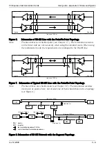
Figure 7. Schematics of Typical RS-485 Line with the Point-To-Point Topology.
Note:
The line utilizes one shielded pair (see Chapter 3.7.). The termination resistors
are shown as passive here, but at least one of them should have active topology
(see Figure 4.).
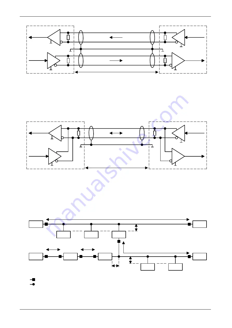
Figure 8. Schematics of RS-485 Network with the Segment Topology.
PCI Express Communication Cards
User guide - Appendix II, Tables and Figures
rev. 10.2009
II - 6
1. device
line max. 1200m
2. device
1. device
2. device
line max. 1200m
line max. 1200m
stub max. 1 m
REP
line max. 1200m
REP
REP
line max. 1200m
line max. 1200m
stub max. 1 m
DEV
DEV
REP
device
repeater
line termination impedance 120 Ohm
short stub without termination impedances
DEV
DEV
DEV
DEV
DEV
DEV
DEV
Summary of Contents for PCI-1482E
Page 1: ...PCI Express Communication Cards User Guide...
Page 18: ...PCI Express Communication Cards User Guide Notes...
Page 19: ......


