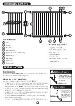
DO NOT mount the Hinge Brackets or Latch Housing on to uneven molding or wall base board trim (skirting board),
as the gate will not function properly.
For plaster/gyprock surface, locate the timber beam or stud behind and mount in this location (mounting on plaster/gyprock
alone is not strong enough and not safe). Do not mount to glass.
DO NOT mount the gate less than 5cm (2in) or more than 7.5cm (3in) above the floor.
Make sure the mounting template is in a straight vertical position.
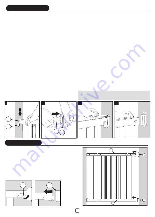
1. Using adhesive tape, attach the mounting template on the
solid wood surface that you have chosen for the hinged side of
the gate.
2. Drill four 3mm (1/8in) diameter starter holes into the
mounting surface at the crosshatch marks on the template.
3. Remove the template from the wall.
4. Drill each hole to a depth of 5cm (2in).
5. Using Hinge Bracket screws, screw the two Hinge Brackets
“F” into the mounting surface with the tabbed edge down.
Tighten the screws until the Hinge Brackets are securely
fastened to the mounting surface.
6. Simultaneously slide the side of both Gate Hinges “G” down
into both Gate Hinge Brackets “F” until it is securely seated (I).
7. Squeeze the Latch Mechanism “D” and slide the upper Latch
Housing “E” over the Latch Mechanism until it snaps into place
(II). Also slide Latch Housing “E2” over the bottom gate rail.
8. Swing the gate into the closed position and extend the Gate
Panels by sliding out, until the gate contacts the latch side of
the mounting surface.
9. Make sure that the top of the gate is level with the floor.
Carefully mark the position of the holes for the upper Latch
Housing “E”, using a pencil (III).
10. Swing the gate out of the way.
Remove the upper Latch Housing “E”.
11. Drill holes as in point 4. Using the correct screws, secure the
upper Latch Housing to the mounting surface.
12. With lower Latch Housing “E2” in place on lower gate rail,
slide the Latch Mechanism into Latch Housing until snaps in.
13. Using a pencil, carefully mark the position of the holes of the
lower latch housing.
14. Squeeze Latch Mechanism, open and swing the gate out of the
way. Remove the lower Latch Housing from the rail.
15. Drill holes, repeat points 4 and 5.
16. Test that the gate is securely installed by firmly shaking the
top rail of gate.
NOTE: If there is a skirting board (base board) to which the gate is to be attached, build up
the wall area where top mounts are to be fitted using a piece of timber of equal thickness.
Alternatively remove the skirting board (base board) prior to mounting gate.
INSTALLATION
F
G
I
II
D E
III
IV
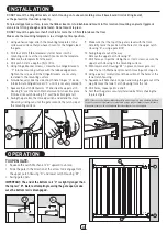
TO OPEN GATE:
• Squeeze the Latch Mechanism “D” upward to unlock;
• Slide the gate in the direction of the arrow to disengage from
the upper Latch Housing “D” and lower Latch Housing “E2”;
• Swing gate open.
IMPORTANT: The end of the bottom rail “C” is slightly longer than
the top rail “B”. Before attempting to swing the gate open, make
sure the bottom rail is disengaged.
OPERATION
D
E
E
B
C
E2
3


