Maintenance (Continued)
4. Hold the motor shaft extension
stationary with pliers, and turn the
impeller counter-clockwise until it is
free from the shaft.
5. Remove the adapter (Ref. No. 5)
from the motor by removing the
capscrews (Ref. No. 17).
REMOVAL OF OLD SEAL
INSTALLATION OF NEW SEAL
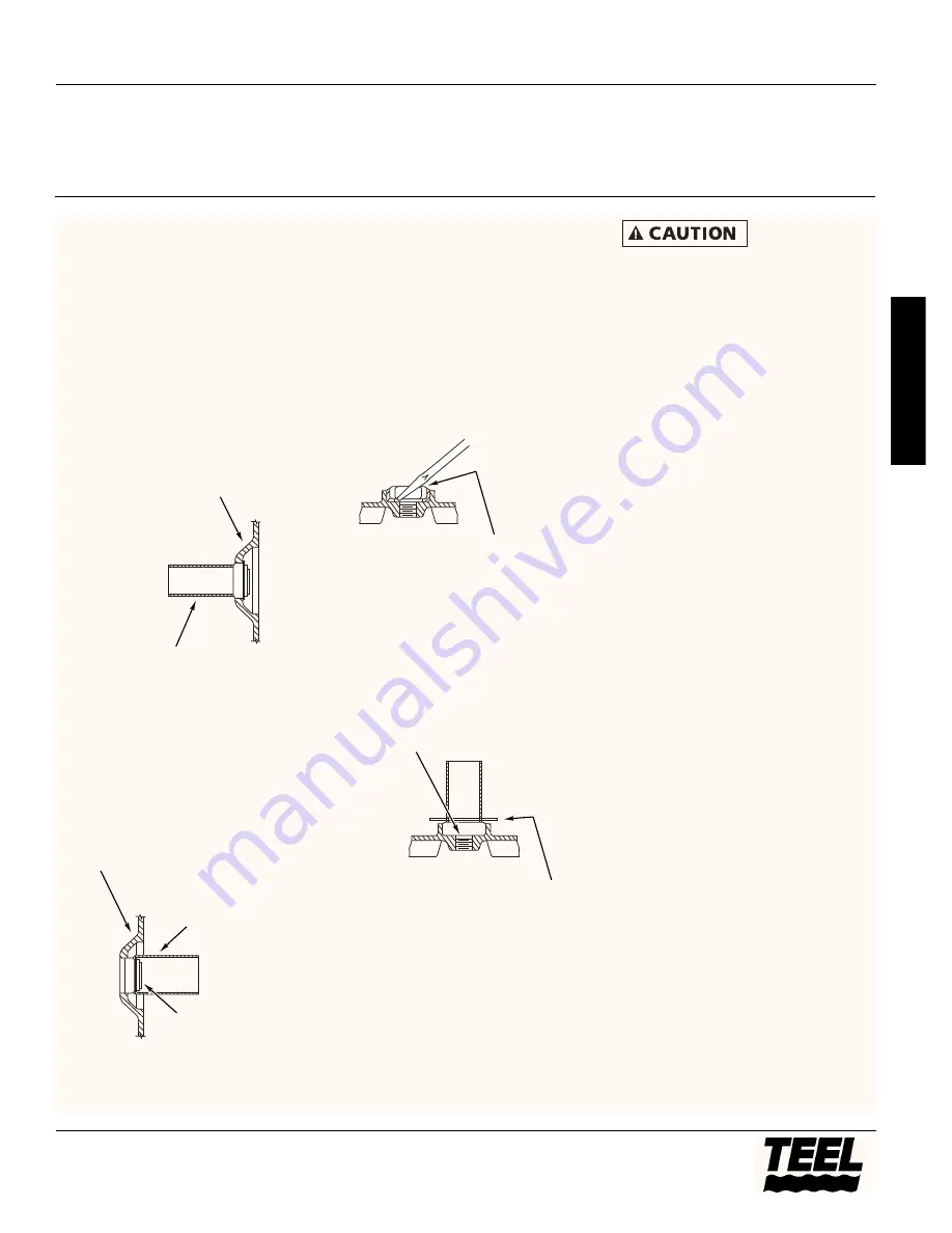
1. Tap the old seal out of the adapter.
Use a piece of pipe or tubing as
shown in Figure 3.
2. Clean the cavity in the adapter.
3. Replacement seal assembly has a dry
lubricant/sealant coating on the
exterior. Do not use any additional
sealing compounds.
4. Press seat into adapter with a tube
or pipe nipple of correct size to
press on the seal rim only (See
Figure 4).
NOTE:
Do not touch or scratch the
polished carbon face of the seal with
the pressing tool.
5. Pry loose the ceramic seal in
impeller, using a screwdriver
between the seat and the cavity in
the impeller (See Figure 5).
6. Lubricate the rubber ring in the
impeller with a soap solution. Press
seat into the impeller cavity
(See Figure 6).
Risk of flooding. If
a tool or pipe is
necessary to press the ceramic seat in
correctly, use a cardboard disc or washer
to protect the highly polished ceramic
surface of the new seal. Remove and
discard disc after assembly.
PUMP REASSEMBLY
Refer to Figure 7, Page 8 for reference
numbers.
1. Loosen shaft extension (Ref. No.
4A), so it may be moved along the
shaft with ease.
2. Replace adapter (Ref. No. 5) on
motor and tighten capscrews (Ref.
No. 17).
3. Make certain the seal faces are
clean.
To set the clearance between the
impeller face and the volute, proceed
as follows:
4. Hold the motor shaft extension
stationary and tighten impeller onto
the shaft.
5. Place volute on adapter without the
gasket and tighten nuts (Ref. Nos. 5,
11, and 16).
6. Push the shaft extension and
impeller toward volute until
impeller touches volute (Ref. Nos.
4A and 10).
7. Tighten set screws (Ref. No. 4B) in
place.
8. Remove volute and install gasket
(Ref. No. 8).
9. Place volute on adapter and tighten
nuts (Ref. No.6). Turn shaft by hand
to make sure impeller does not bind
or drag.
Models 4RH36, 4RH37, 4RH38, 4RH39, and 4RH40
7
Teel Operating Instructions and Parts Manual
E
N
G
L
I
S
H
Figure 4 – Replacing stationary part of
seal
Pump adapter
Tube for pressing
in seal. Press on
flange only
Polished carbon face of
seal. Do not scratch
Figure 5 – Pry out rotating part of seal
from impeller
Pry out rotating part of
seal from impeller
Figure 6 – Replacing rotating part of
seal in impeller
Lubricate rubber ring
with soap solution
Use cardboard disk
or washer to protect
ceramic surface when
pressing new seal into
impeller
Figure 3 – Press out stationary part of
seal
Pump adapter
Tube to press out
stationary part of seal
®


