UK
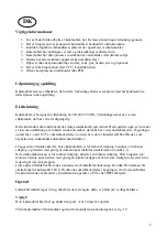
Important safety instructions
1.
To obtain full use of the cabinet, we recommend reading this instruction manual.
2.
It is the user’s responsibility to operate the appliance in accordance with the instructions
given.
3.
Contact your dealer immediately in case of any malfunctions.
4.
Place the cabinet in a dry and ventilated place.
5.
Keep the cabinet away from strongly heat-emitting sources and do not expose it to direct
sunlight.
6.
Always keep in mind that all electrical devices are sources of potential danger.
7.
Do not store inflammable material such as thinner, gasoline etc. in the cabinet.
8.
We declare that no asbestos nor any CFC are used in the construction.
9.
The oil in the compressor does not contain PCB.
Unpacking and installation
Remove the wooden pallet and the packing. External surfaces are supplied with a protection foil,
which must be removed before installation
Electrical connecting
The cabinet operates on 230 V/50 Hz.
The wall socket should be easily accessible.
All earthing requirements stipulated by the local electricity authorities must be observed. The
cabinet plug and wall socket should then give correct earthing. If in doubt, contact your local
supplier or authorized electrician.
The flexible cord fitted to this appliance has three cores for use with a 3-pin 13-Amp or 3-pin 15-
Amp plug. If a B.S. 1363 (13-Amp) fused plug is used, it should be fitted with a 13-Amp fuse.
The wires in this mains lead are coloured in accordance with the following code:
Green/Yellow: Earth, Blue: Neutral, Brown: Live.
The main electrical connections must be done by skilled electricians.
Start-up of the cabinet
Before use, we recommend that the cabinet is cleaned, see the section on maintenance and cleaning.
Important !
If the cabinet has been vertically placed during transport, please wait 2 hours before starting up the
cabinet.
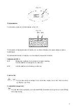
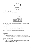
Connect the cabinet to a socket and turn on the switch on the control panel, see fig. 1.9.
13
Summary of Contents for Interlevin REFRIGERATION CW Series
Page 38: ...RUS 1 2 3 4 5 CFC PCB 220 240 V 50Hz 2 1 9 1 9 6 7 8 9 37...
Page 39: ...2 0 P 2 0 DP2 DP1 DP2 DP1 5 Pof Pon 38...
Page 40: ...5 47 PF1 39...
Page 41: ...40...
Page 42: ...41...
Page 43: ...42...
Page 45: ...44...
Page 46: ...45 45...

