18
Spare Parts
Use original spare parts only.
Replace components before they are worn out. Perform regular maintenance checks, as
detailed in the “MAINTENANCE” section.
Warranty
In order to enjoy the MANUFACTURER’S warranty, users shall strictly follow all the instructions
specified in this manual, in particular they shall:
- use the hood only for its intended purposes;
- perform continuous and scrupulous maintenance 0perations;
- allow the use of the hood only to persons with proven skills and know-how.
Failure to comply with the instructions contained in this manual will immediately void the
manufacturer’s warranty.
INSTALLATION INSTRUCTIONS
-
Installation and electrical connection operations shall be performed according to these
instructions and by qualified and specialized personnel.
-
Wear protective gloves before and during installation.
-
Check that no accessory material provided with the appliance (manuals, accessories,
etc) is placed inside the hood: in such a case remove and keep them.
-
Figures shown in this installation manual might also refer to different aesthetics of the
appliance: in any case use, installation and maintenance instructions remains the same
.
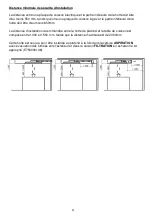
Minimum installation safety distance
The distance between an electric hob and the lower part of the hood must be at least 550 mm,
while between a gas hob and the lower part of the hood must be minimum 650 mm.
The recommended installation distance between the ceiling hood and the hob is between 1300
and 1500mm, while the maximum distance is 2000mm.
This hood is designed to be installed on the ceiling both in the
ASPIRATING
version with
evacuation of fumes to the outside and in the
FILTERING
version by purchasing the appropriate
kit (E750000148).
Summary of Contents for 113100004
Page 1: ...User Manual EN PT FR IT DE PL ES www teka com ...
Page 2: ...2 Fig 1 Fig 2 ...
Page 3: ...3 Fig 3 Fig 4 ...
Page 4: ...4 Fig 5 Fig 6 X4 LAMP CABLE DISCONNECTION ...
Page 5: ...5 Fig 7 Fig 8 X4 MOTOR CABLE DISCONNECTION ...
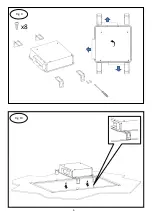
Page 6: ...6 Fig 9 Fig 10 x8 ...
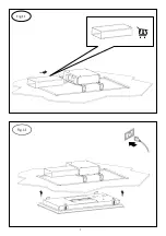
Page 7: ...7 Fig 11 Fig 12 ...
Page 8: ...8 Fig 13 Fig 14 X12 MOTOR CABLE CONNECTION ...
Page 9: ...9 Fig 15 LAMP CABLE CONNECTION Fig 16 X4 ...
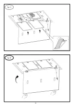
Page 10: ...10 Fig 17 Fig 18 ...
Page 100: ...100 www teka com E461000129 Rev 1 ...


