21
HOOD LED INDICATION
In the hood body there is a LED that indicates the operating status of the motor running at
speed according to these criteria:
Engine OFF: LED off;
1st speed motor Blue LED color;
2nd speed motor Green LED color;
3rd speed motor Yellow LED col
or;
4th speed motor Red LED color;
5th Speed Motor (Intensive) Magenta LED color (Flashes intermittently for 1 second for 6
minutes and then returns to 4th speed).
6th Speed Motor (Intensive) Pink LED color (Flashes intermittently for 1 second for 6 minutes
and then returns to 4th speed).
By activating the timer, the corresponding color LED, depending on the set speed, flashes
intermittently for 1 second, at the end of 15 minutes, in non-intensive speeds, the engine turns
off and not the lighting. As for the intensive speeds, when the timer is activated, it remains at
the set speed for the first 6 minutes and then ends the remaining 9 minutes at the 4th speed.
In the Clean Air function, the light blue LED remains steady, the motor switches to 6th speed
and after 6 minutes the motor and not the lighting switches off.
In the Fresh Air function, the Blue LED flashes intermittently for 5 seconds, with the hood off,
the engine starts at 1st speed for 10 minutes and then remains off for 50 minutes and so on
until the function is switched off.
Metal grease filter cleaning signal
After 30 hours of operation, the Green LED will start flashing for 20 seconds indicating to clean
the filters. To reset the filters, with the hood off, press the “P0” key for 3 seconds while the LED
is flashing.
Long-life or ceramic filter cleaning signal
After 120 hours of operation, the Red LED will start flashing for 20 seconds indicating to clean
the filters. To reset the filters, with the hood off, press the “P0” key for 3 seconds while the LED
is flashing.
Each time a button on the remote control is pressed, the hood will emit an acoustic signal to
confirm the reception of the signal.
Summary of Contents for 113100004
Page 1: ...User Manual EN PT FR IT DE PL ES www teka com ...
Page 2: ...2 Fig 1 Fig 2 ...
Page 3: ...3 Fig 3 Fig 4 ...
Page 4: ...4 Fig 5 Fig 6 X4 LAMP CABLE DISCONNECTION ...
Page 5: ...5 Fig 7 Fig 8 X4 MOTOR CABLE DISCONNECTION ...
Page 6: ...6 Fig 9 Fig 10 x8 ...
Page 7: ...7 Fig 11 Fig 12 ...
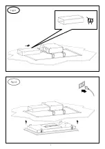
Page 8: ...8 Fig 13 Fig 14 X12 MOTOR CABLE CONNECTION ...
Page 9: ...9 Fig 15 LAMP CABLE CONNECTION Fig 16 X4 ...
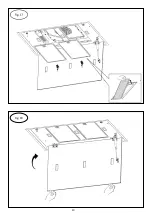
Page 10: ...10 Fig 17 Fig 18 ...
Page 100: ...100 www teka com E461000129 Rev 1 ...

