23
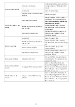
The motor does not work
Disconnected connector
Hook up the motor connector as shown
on page 6, Picture 7 of the instruction
manual.
No electricity
Check the motor driver.
Electricity arrives but the motor does
not work
Replace the motor.
The Remote Control is not
working
Low remote control battery
Replace battery as shown on page 12,
Picture 20 of the instruction manual.
Make sure that the battery is inserted
with the correct polarity.
Remote control is not synchronised
with the hood
Synchronise the remote control as
described in the instruction manual
from page 20.
On/off switch is in position 0
Set the on/off switch to position 1 as
shown on page 4, Picture 4 of the
instruction manual.
Hood is not working
No electricity
Check the power cable.
Remote control is not synchronised
with the hood
Synchronise the remote control as
described in the user manual from page
20.
Electrical system problems
Check the power supply on the
electronic board.
On/off switch is in position 0
Set the on/off switch to position 1 as
shown on page 4, Picture 4 of the
instruction manual.
Hood aspirates little air
Soiled aluminium filters
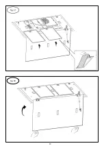
Remove the filters as shown on page
11, Picture 17 of the operating manual
and wash the filters.
Green LED flashes for 20
seconds
Metal grease filter cleaning indicator
Reset the filters when the hood is
turned off pressing the "P0" button on
the remote control for 3 seconds while
the LED flashes as shown on page 22 of
the instruction manual.
Red LED flashes for 20
seconds
Long-life or ceramic filter cleaning
indicator
Reset the filters when the the hood is
turned off pressing the button “P0” on
the remote control for 3 seconds while
the LED flashes as shown on page 22 of
the user manual.
Summary of Contents for 113100004
Page 1: ...User Manual EN PT FR IT DE PL ES www teka com ...
Page 2: ...2 Fig 1 Fig 2 ...
Page 3: ...3 Fig 3 Fig 4 ...
Page 4: ...4 Fig 5 Fig 6 X4 LAMP CABLE DISCONNECTION ...
Page 5: ...5 Fig 7 Fig 8 X4 MOTOR CABLE DISCONNECTION ...
Page 6: ...6 Fig 9 Fig 10 x8 ...
Page 7: ...7 Fig 11 Fig 12 ...
Page 8: ...8 Fig 13 Fig 14 X12 MOTOR CABLE CONNECTION ...
Page 9: ...9 Fig 15 LAMP CABLE CONNECTION Fig 16 X4 ...
Page 10: ...10 Fig 17 Fig 18 ...
Page 100: ...100 www teka com E461000129 Rev 1 ...


