

18
ENG
1
150/125 mm reduction.
1 Anti-recoil
valve.
1
Support for tubecover.
1
Hood support.
2
Wall support.
6
Wall plugs (Ø8 x 40).
6
Long bolts (Ø5 x 45).
2
Wall plugs (Ø6 x 30).
2
Long bolts (Ø4 x 30).
2
M6 washers.
2
M4 washers.
2
Screws (Ø3.9 x 13).
8
Screws (Ø4 x 12).
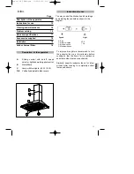
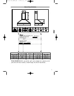
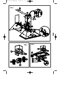
Fig. 1 (Page. 19)
On installing the kitchen hood make sure
that the Safety Instructions set out on page
14 are complied with.
To obtain optimum performance, the external
conduct must be no more than FOUR
METRES LONG, have more than two 90°
angles and its diameter must be at least Ø120.
1) Using the attached template, trace and drill
the points for fitting the wall plugs onto the wall
(A1) (Ø8 x 40).
2) Attach the Supports (O) to the wall using the
long bolts (Q) (Ø5 x 45) as in figure 1.
3) Fit the support (K) to the body of the hood
using the long bolts (A4) (M4 x 12), as
indicated in figure 1.
4) Hang the kitchen hood onto the mounted
supports (O). Straighten the appliance by
tightening the long bolts (L) (M4 x 12).
5) Trace the location of the long bolts (S) (Ø 5
x 45).
6) Take the kitchen hood off.
7) Drill into the wall and fit the wall plugs (R).
8) Hang the kitchen hood; tighten the screws
(M) (M4x12) with the washers (A3) (M4) and
the long bolts (S) (Ø 5x45) with the washers
(T).
9) Mount the tubecovers. Lift the upper
tubecover up to the desired height and mark its
shape on the wall. Remove the tubecovers.
10) Fit the clips (F) to the support (C).
11) Centre the support (C) around the shape
marked; trace and drill the fixing points for the
wall plugs (E) (Ø6 x 30). Attach the support (C)
with the long bolts (D) (Ø4x30).
12) Fit the part (A) if the inner tube (not
supplied) is Ø150 or (A)+(B) if it is Ø120.
13) Attach the inner tube with a clamp (not
supplied) to (A) or (B) as the case may be.
14) Once the inner tube is fitted, fit the lower
tubecover around the extractor fan outlet and
attach the upper tubecover with the screws
(G).
When exterior gas extraction is not possible,
then the kitchen hood may be set to purify the
air by recycling it through active charcoal
filters.
The active charcoal filters have an active life of
between three to six months, depending on
the individual conditions of use. These filters
cannot be washed nor regenerated. They must
be replaced once their useful life comes to an
end.
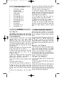
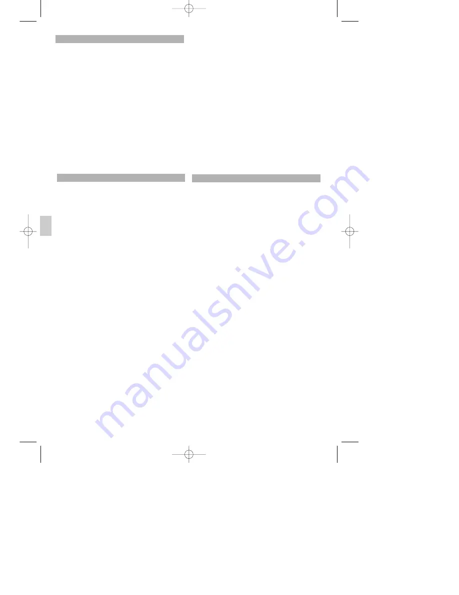
SET type 1 - Fig. 2 (Page.19)
1) Put the filters into the lateral draught section
of the motor making the holes in the filters
match up (A) with the pivots (B) of the motor
carcass. Turn as indicated in the diagram.
2) Remove the tubecovers. Fit the diffuser (C)
into the inside of the lower tubecover with the
screws (D). Mount the tubecovers.
SET type 2 - Fig. 3 (Page. 19)
1) Fit the nut-supports (F) onto the body of the
kitchen hood.
2) Attach the supports (B) with the screws (E)
onto the nuts (F).
3) Mount the carbon filters (A) introducing the
anchorages into the grooves of the supports.
4) Remove the tubecovers. Fit the diffuser (C)
into the inside of the lower tubecover with the
screws (D). Mount the tubecovers.
Active charcoal filters (Optional)
Installation
Accesories supplied
Manual DE TEKA2.qxd 15/02/2005 9:07 Page 18


