background image

12

Gea-Top/001

Switch on the extractor fan a few minutes before
you start to cook in order to ensure that a steady
air flow has been established before fumes
appear.

Allow the extractor fan to run for several minutes
after you have finished cooking (between 3 to 5
minutes) in order to expel all the grease from the
outlet duct. This prevents the return of grease,
smoke and smells.

 2.

Instructions for use

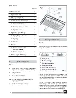
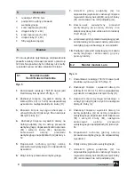
fig. 2

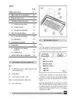
You may control the kitchen hood by operating
the controls as shown in the diagram.

Off

Minimum speed

Medium speed

Maximum speed

Light On

Light Off

fig. 2

Index

Page

Safety instructions

11

1.

Description of the appliance

12

2.

Instructions for use

12

3.

Cleaning and maintenance

13

3.1

Cleaning the hood body

13

3.2

Problem solving

13

3.3

Changing the light bulbs

13

4.

Size and specifications

14

4.1

Technical specifications

14

4.2

Dimensions

14

5.

Accessories supplied

15

6.

Installation

15

6.1

Installing: Trenti / Nubero
Ventoline

15

6.2

Installing: Laro

15

7.

Active carbon filters (optional)

16

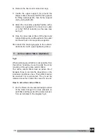
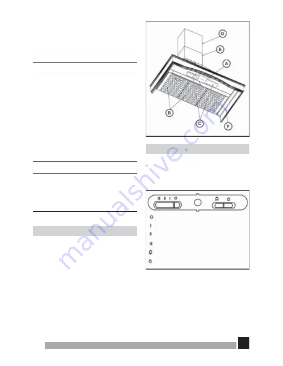
 1.     Descriptions of the appliance

fig. 1

A

On/Off Push button, speed selector, light
and working pilot.

B

Metal filters.

C

Lamp with two bulbs - 40W.

D,E Vertically adjustable tubecovers.

F

Decorative part

fig.1

UK

Summary of Contents for Kitchen Hoods

Page 1: ...1 Gea Top 001 Instructions Manual Kitchen Hoods LARO 90 TRENTI 90 VENTOLINE 60 90 NUBERO 60 90 Instrukcja obsługi i montażu Wyciąg kuchenny LARO 90 TRENTI 90 VENTOLINE 60 90 NUBERO 60 90 ...

Page 2: ...rzewodami oddymiającymi które służą do odprowadzania spalin urządzeń nie zasilanych energią elektryczną Z uwagi na gromadzący się tłuszcz na filtrach metalowych i wnętrzu obudowy wyciągu istnieje niebezpieczeństwo jego samozapłonu Dlatego filtry i obudowę należy regularnie czyścić co najmniej raz w miesiącu Dolna powierzchnia wyciągu powinna znajdować się co najmniej 50 cm nad palnikami elektryczn...

Page 3: ...rednia siła ciągu Duża siła ciągu Włącznik oświetlenia Wyłącznik oświetlenia Rys 2 1 Opis urządzenia Rys 1 A Włącznik Wyłącznik przełącznik światła i regulator siły ciągu z lampką kontrolną B Filtry metalowe C Oświetlenie 2 x 40 W D E Osłona przewodu wentylacyjnego z regulacją wysokości F Część dekoracyjna wyciągu Spis treści Strona Istotne informacje 2 1 Opis urządzenia 3 2 Obsługa urządzenia 3 3...

Page 4: ...Przed wezwaniem Punktu Serwisowego należy dokonać sprawdzenia następujących usterek Problem Wyciąg nie pracuje Wyciąg nie pochłania prawidłowo lub wibruje Żarówki nie świecą się Przyczyna Kabel nie jest podłączony do zasilania Nie ma prądu w gniazdku Filtry są nasycone tłuszczem Przeszkoda w swobodnym przepływie powietrza Żarówki przepaliły się Żarówki poluzowały się Rozwiązanie Podłączyć przewód ...

Page 5: ...mm D mm E mm F mm MIN MAX TRENTI 90 900 502 523 1023 98 218 157 MODEL A mm B mm C mm D mm E mm F mm MIN MAX VENTOLINE 60 600 502 488 988 122 157 218 VENTOLINE 90 900 502 494 994 122 157 218 MODEL A mm B mm C mm D mm E mm F mm MIN MAX NUBERO 60 600 504 488 988 98 152 142 NUBERO 90 900 510 483 983 98 152 142 TEKA zastrzega sobie prawo do zmian technicznych swoich produktów w zakresie jakim jest to n...

Page 6: ...órną podpórkę G na odpowiedniej wysokości zaznaczyć miejsca i wywiercić otwory na kołki M wkręcić śruby M i zamocować na nich podpórkę G 8 Zamocować wewnętrzny przewód wentylacyjny za pomocą klamry nie dołączona do wylotu silnika lub do redukcji 150 120 rys 7 9 Jeżeli wewnętrzny przewód wentylacyjny jest zamontowany zamocować osłony przewodu wentylacyjnego zahaczając je za podpórki 10 Podłączyć pr...

Page 7: ...przewód wentylacyjny do kanału wentylacyjnego i zamocować go przy pomocy klamry 7 Filtry z węgla aktywnego Rys 8 W przypadku braku możliwości odprowadzania oparów na zewnątrz należy zainstalować filtry z węgla aktywnego Skuteczność działania filtrów węglowych wynosi od 3 do 6 miesięcy zależnie od intensywności użycia Filtrów tych nie można czyścić ani regenerować Jak zamontować filtry węglowe Zało...

Page 8: ...8 Gea Top 001 Czyszczenie filtrów metalowych Rys 3 6 1 Montaż modeli Trenti Nubero Ventoline Rys 5 Rys 5a Rys 5b Rys 5c PL ...

Page 9: ...9 Gea Top 001 6 2 Montaż modelu Laro Rys 6 Rys 6a Rys 6b Rys 6c PL ...

Page 10: ...10 Gea Top 001 Montaż przewodu wentylacyjnego Rys 7 Filtry z węgla aktywnego Rys 8 PL ...

Page 11: ...ce e g gas cookers then the room must have sufficient ventilation Excessive fat accumulation in the kitchen hood and metal filters is a fire risk and may also cause dripping therefore the inside of the kitchen hood and the metal filters must be cleaned at least once a month The lower part of the kitchen hood must be fitted at least 50 cm over electric hobs and 65 cm over gas or mixed hobs FOLLOW T...

Page 12: ...mum speed Medium speed Maximum speed Light On Light Off fig 2 Index Page Safety instructions 11 1 Description of the appliance 12 2 Instructions for use 12 3 Cleaning and maintenance 13 3 1 Cleaning the hood body 13 3 2 Problem solving 13 3 3 Changing the light bulbs 13 4 Size and specifications 14 4 1 Technical specifications 14 4 2 Dimensions 14 5 Accessories supplied 15 6 Installation 15 6 1 In...

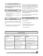
Page 13: ...ssive detergents or polish may damage the metallic surface blackening it although this will not affect its fat retention capacity Once clean leave them to dry off and then fit them onto the kitchen hood 3 3 Changing the light bulbs Proceed as follows Remove the metal filters Change the broken burnt out lamp Maximum lamp power is 40W Fit the metal filters Problem solving Proceed with the following ...

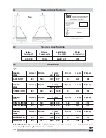
Page 14: ... mm D mm E mm F mm STEEL MIN MAX TRENTI 90 900 502 523 1023 98 218 157 PAINTED A mm B mm C mm D mm E mm F mm STEEL MIN MAX VENTOLINE 60 600 502 488 988 122 157 218 VENTOLINE 90 900 502 494 994 122 157 218 PAINTED A mm B mm C mm D mm E mm F mm STEEL MIN MAX NUBERO 60 600 504 488 988 98 152 142 NUBERO 90 900 510 483 983 98 152 142 TEKA INDUSTRIAL S A reserves the righ to make changes and corrections...

Page 15: ... and lift it up to the desired height and mark its shape on the wall 6 Remove the fixed and mobile chimneys 7 Centre the upper support G around the shape marked trace and drill the fixing points for fitting wall plugs M then fix the support G by using bolts M 8 Attach the inner tube possibly flexible with a clamp not supplied to the motor s air outlet or to the 150 120 reduction as the case may be...

Page 16: ... scavenging pipe to the outdoor duct and fix it with a pipe tightening clamp 7 Active carbon filters Optional fig 8 When exterior gas extraction is not possible then the kitchen hood may be set to purify the air by recycling it through active carbon filters The active carbon filters have an active life of between three to six months depending on the individual conditions of use These filters canno...

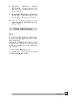
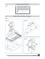
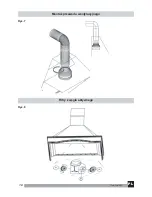
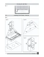
Page 17: ...17 Gea Top 001 Cleaning the metal filters fig 3 6 1 Installing Trenti Nubero Ventoline fig 5 fig 5a fig 5b fig 5c UK ...

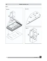
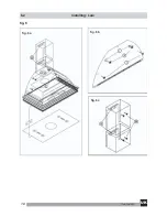
Page 18: ...18 Gea Top 001 6 2 Installing Laro fig 6 fig 6a fig 6b fig 6c UK ...

Page 19: ...19 Gea Top 001 How to assemble the out door scavenging pipe fig 7 Active charcoal filters fig 8 UK ...

Page 20: ... LTD TEKA THAILAND CO LTD TEKA B V TEKA TEKNIK MUTFAK A S TEKA PRODUCTS UK LTD TEKA USA INC TEKA ANDINA S A 43 32 56 86 42 33 30 36 62 60 52 48 351 7 65 66 31 90 44 1 58 1 86680 0 2466 8740 2 273 19 45 21 6236 2375 05 4921 0478 1 5836 4830 210 9760283 1 354 21 10 21 39052 74 3 762 01 600 555 762 04 90 22 738 32 80 234 32 95 00 095 737 4689 6 73 42415 2 5164954 79 345 15 89 212 274 61 04 1235 86 19...

Reviews: