20
Gea-Top/001
UK
PL
ES
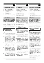
5. Akcesoria
1. redukcja 120/150 mm
2. podpórki do os³ony przewodu
wentylacyjnego
2. korki rozporowe (9 x 40)
2. d³ugie œruby (9 x 40)
6. korki rozporowe (5 x 40)
6. d³ugie œruby (5 x 40)
2. filtry wêglowe (opcja)
6. Monta¿
W celu uzyskania optymalnego
odprowadzenia powietrza nale¿y
stosowaæ przewód o przekroju 120
mm. Nie powinien byæ on d³u¿szy
ni¿ 4 metry i posiadaæ wiêcej ni¿
dwa kolanka 90 stopni.
6.1 Monta¿ modeli:
Trenti/ Nubero/Ventoline
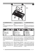
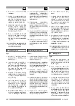
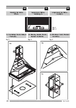
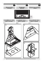
Rys. 5
1.
Zamontowaæ redukcjê 150/120
nawet jeœli œrednica wylotu
wynosi 125 (Rys. 7);
2.
Zaznaczyæ miejsca i wywierciæ
otwory do ko³ków (H 9 x 40) i (L 5
x 30) na odpowiedniej wysokoœci
a nastêpnie dokrêciæ œruby (H);
3.
Zawiesiæ korpus wyci¹gu
zahaczaj¹c o uchwyt (I) œruby (H)
jak na rys. 5b a nastêpnie
dokrêciæ œruby (L);
4.
Zaznaczyæ miejsca i wywierciæ
otwory na doln¹ podpórkê (G) do
os³ony przewodu wentylacyjnego,
dopasowaæ korki rozporowe (M) i
wkrêciæ œruby (M), nastêpnie
zamocowaæ os³onê przewodu
wentylacyjnego na podpórkach (G)
jak na rys. 5c;
5.
Dopasowaæ ruchom¹ (górn¹)
os³onê przewodu wentylacyjnego
do odpowiedniej wysokoœci;
6.
Zdj¹æ os³ony przewodu
wentylacyjnego;
5. Accessories supplied
1. 120/150 mm reduction
2. wall support for tubecover
2. wall plugs (Ø9x40)
2. long bolts (Ø9x40)
6. wall plugs (Ø5x40)
6. long bolts (Ø5x40)
2. active carbon filters (optional)
6. Installation
On installing the kitchen hood make
sure thet Safety Instructions set out
on page 14 are complied with.
To obtain optimum performance, the
external duct must not to be more
than FOUR METERS LONG, have
no more than two 90° angles and its
diameter must be at least Ø120.
6.1 Installing: Trenti /
Nubero / Ventoline
fig.5
1.
Mount the 150/120 reduction
whenever the air discharge tube
is Ø125 (fig.7);
2.
Trace and drill the points for
fitting the wall plugs (H Ø9x40)
and (L Ø5x30) onto the wall at
the desired height by leaning
the hood on the wall, then
tighten the long bolts (H);
3.
Hang the kitchen hood, hooking
its support (I) onto the long bolts
(H) as in fig.5b and then tighten
the long bolts (L);
4.
Trace and drill the location of
the lower support (G) of the
tubecover, fit the wall plugs (M)
and fix it by using the bolts (M),
then hook the fixed chimney to
its support (G) as in fig.5c;
5.
Mount the mobile chimney and
lift it up to the desired height
and mark its shape on the wall;
5. Accesorios suministrados
1. reducción 120/150 mm
2. soporte de pared para tapa del
tubo
2. tacos (Ø9x40)
2. pernos (Ø9x40)
6. tacos (Ø5x40)
6. pernos (Ø5x40)
2. Filtros de carbón activo (opcional)
6. Montaje
Para efectuar el montaje de la cam-
pana de cocina, sujétese a las
instrucciones de la página 14.
Para obtener el máximo rendimiento
de la misma, los conductos externos
no deben tener más de CUATRO
METROS DE LARGO, ni más de dos
ángulos de 90 °y el diámetro de los
mismos debe ser por lo menos de Ø120.
6.1 Montaje: Trenti / Nubero /
Ventoline
fig.5
1.
Monte el mecanismo de reducción
de 150/120 en los casos que se
utilice un tubo de salida del aire de
Ø125 (Fig.7);
2.
Trace y perfore los orificios para la
fijación de los tacos ((H Ø9x40) y (L
Ø5x30) en la pared a la altura
deseada apoyando la campana
contra la pared y luego
atornillándola con los pernos (H);
3.
Cuelgue la campana de cocina,
enganchando sus soportes (I) en
los pernos (H) como se muestra
en la Fig. 5b y luego atornillar
los pernos (L);
4.
Trace y perfore la ubicación del
soporte inferior (g) de la tapa del
tubo, ponga los tacos (M) y fíjelos
utilizando los pernos (M), luego
enganchar la chimenea fija a su
soporte (G) como se ilustra en la
figura Fx;
5.
Monte la chimenea móvil y
levántela hasta la altura donde
la desea colocar y marque su fi-
gura en la pared;
Summary of Contents for LARO 90
Page 32: ...32 Gea Top 001 UK PL ES ...
Page 34: ...34 Gea Top 001 UK PL ES ...
Page 35: ...FR DE GR 35 Gea Top 001 ...

