1
of
12
©
2008 W
544
-
12/08
W 544
12/08
tekmarNet
®
4 Thermostat 544
- Wiring Brochure
Overview
Information
Brochure
Choose controls
to match
application
1
Application
Brochure
Design your
mechanical
applications
2
Layout
Brochure
Rough-in
wiring
instructions
3
Wiring
Brochure
Wiring and
installation of
specific control
4
Job
Record
Record settings &
wiring details for
future reference
6
Data
Brochure
Control settings
and sequence of
operation
5
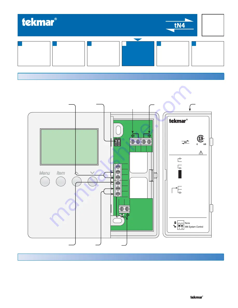
The following brochure describes how to wire the tekmar tekmarNet
®
4 (tN4) thermostat 544. The 544 has outputs for:
one heat stage, one cooling stage and one fan. The 544 has inputs for two auxiliary sensors. The wiring of 544 thermostat
is simple and cost effective.
Table of Contents:
Definitions .......................................................................2
Rough-In Wiring .............................................................2
Remove the Wiring Cover ..............................................3
Mounting the Thermostat ...............................................3
Wiring Symbols ...............................................................3
Electrical Drawings ......................................................3-7
Wiring the Thermostat .................................................8-9
Troubleshooting the Wiring ........................................... 10
Testing the Wiring ......................................................... 11
Technical Data .............................................................. 12
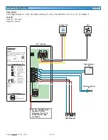
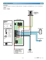
tNt 544
One Stage Heat, One Stage Cool, One Fan
Power: 24 V (ac) ±10% 60 Hz 1.5 VA
Relays: 24 V (ac) 2 A
G1
Rc
Y1
Com
S2
S1
tN4
C
R
Rh1
W1
Fan 1 Relay
G1
Fan 1 Relay
Power Cooling
Cool 1 Relay
Sensor Common
Sensor 2
Sensor 1
tekmarNet 4
Power Neutral
Power 24 V (ac)
Heat 1 Relay
Heat 1 Relay
DIP Switch Functions
992-03
Meets Class B: Canadian ICES, FCC Part 15
®
No Power
To isolate
relay, cut
jumper
Terminal Functions
Y1 Rc G1 G1
R
C
tN4
S1
S2
Com
W1
Rh1
24 V (ac)
Power
tN4
Network
1st Stage
Cooling
1st Stage
Heating
DIP
Switches
Auxiliary
Sensors
1st Stage
Fan
Wiring
Cover


