background image


Manuel d’instruction 


www.lutechenergie.com 

Summary of Contents for tekmarNet 4 Setpoint Control 161

Page 1: ... Manuel d instruction www lutechenergie com ...

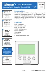
Page 2: ...ngs and sequence of operation 4 5 D161 08 07 tekmarNet 4 Setpoint Control 161 Data Brochure 1 of 36 2007 D161 08 07 The Setpoint Control 161 is a single stage heat setpoint control that can operate on an On Off differential or can operate on Pulse Width Modulation The control includes special modes for hot tub domestic hot water tank and radiant floor applications Introduction tN4 Compatible On Of...

Page 3: ...play and DIP Switches 2 Dip Switches 2 Access Levels 3 Display 3 Symbol Description 4 User Interface 4 Application Overview 5 On Off Differential 5 Pulse Width Modulation 6 Display Menus 7 VIEW Menu 7 ADJUST Menu 10 SCENE Menu 15 SCHEDULE Menu 16 MISCELLANEOUS Menu 17 Sequence of Operation 19 Mode 1 On Off Setpoint 19 Mode 2 Hot Tub 19 Mode 3 DHW Tank 20 Mode 4 Floor 21 Remote Enable Disable 22 Se...

Page 4: ...vel In the Secure access level all settings including the temperature cannot be changed For more information see the Miscellaneous MISC Menu section In the following menu tables the access level the item is visible in is shown in the access column To adjust the Access Level 1 Set the Unlock Lock DIP switch to the unlock position If a tN4 System Control is connected to the 161 the Unlock Lock DIP s...

Page 5: ...ation of the setpoint control Use the four push buttons below the LCD Menu Item Up Down to select settings As the settings are entered record the settings in the Job Record J161 User Interface Menu The menus display in the Menu Field at the left of the LCD Up to 5 menus are available VIEW ADJUST SCENE SCHD Schedule MISC Miscellaneous To select a menu press and release the Menu button Item In each ...

Page 6: ...default item after 60 seconds of button inactivity Application Overview The Setpoint Control 161 is designed to support four different applications The items shown in the VIEW and ADJUST Menu change depending on the Application Mode Set the application mode as follows 1 Setpoint 2 Hot Tub 3 DHW Tank 4 Floor The VIEW and ADJUST menus list which of the four application items are visible based upon t...

Page 7: ...rottling range is fixed at 3 F 1 5 C The cycle length is either the same as the tN4 system control or when a tN4 system control is not present the cycle length is fixed at 15 minutes Mode 3 DHW Tank Relay 1 On Off Differential Operation The On Off Differential operates by centering a differential range around the target setpoint temperature On Off differentialsarebestsuitedtoheatingloads that quic...

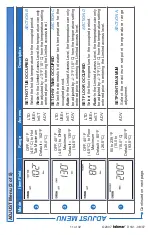
Page 8: ...Time counts down to 0 00 hours Cancel the override by pressing the Up and Down buttons together at the same time or through the user switch or gateway Note This item is only available when a programmable setback schedule or normally unoccupied has been selected 1 31 to 266 F 35 0 to 130 0 C SEC LTD USEr InST ADV SETPOINT SECTION A Displays the measured setpoint sensor temperature The VIEW menu ite...

Page 9: ... F 35 0 to 130 0 C SEC LTD USEr InST ADV DHW TANK SECTION C Displays the measured domestic hot water tank temperature 4 31 to 266 F 35 0 to 130 0 C SEC LTD USEr InST ADV FLOOR SECTION D Displays the measured floor temperature 1 OFF 4 F 20 0 C to Setpoint Maximum variable USEr InST ADV SET SETPOINT SECTION A Display the desired temperature VIEW MENU VIEW Menu 2 of 3 Continued on next page ...

Page 10: ...ximum variable USEr InST ADV SET FLOOR SECTION D Display the desired temperature 1 2 3 4 31 to 266 F 35 0 to 130 0 C InST ADV SUPPLY TEMP OF tN4 BUS SECTION L Actual water temperature of the tN4 bus for heating Note This item is only available when the setpoint control is connected to a tN4 System Control DIP switch 2 is set to tN4 System Control and the Heat Source item in the ADJUST menu is set ...

Page 11: ...ERATION SECTION B Select to either heat or turn off the hot tub 1 OFF 4 F 20 C to Setpoint Maximum Default 160 F 71 0 C LTD USEr InST ADV SET SETPOINT OCCUPIED SECTION A Select the setpoint temperature for the occupied period Note In the Limited Access Level the temperature can only be adjusted by 3 F 1 5 C from the temperature setting entered prior to entering the Limited access level The ADJUST ...

Page 12: ...water tank temperature for the occupied period Note In the Limited Access Level the temperature can only be adjusted by 3 F 1 5 C from the temperature setting entered prior to entering the Limited access level 4 OFF 40 F 4 5 C to Floor Maximum Default 80 F 26 5 C LTD USEr InST ADV SET FLOOR OCCUPIED SECTION D Select the floor temperature for the occupied period Note In the Limited Access Level the...

Page 13: ...40 F 60 0 C ADV DHW MAXIMUM SECTION C Select the maximum domestic hot water tank temperature range adjustment 4 50 to 110 F 10 0 to 43 5 C Default 85 F 29 5 C ADV FLOOR MAXIMUM SECTION D Select the maximum floor temperature range adjustment 1 2 3 1 to 40 F 0 5 to 22 0 C Default 10 F 5 5 C InST ADV DIFFERENTIAL Select the differential to cycle on and off around the setpoint temperature ADJUST Menu ...

Page 14: ... desired supply water temperature required on the tN4 bus to heat the setpoint load during the occupied period Note This item is only available when DIP switch 2 is set to tN4 System Control and the Heat Source item in the ADJUST menu is set to hydronic HYDr 1 2 3 4 On OFF Default OFF InST ADV PRIORITY SECTION L Select if the setpoint control has priority over the heating system Note This item is ...

Page 15: ...eat Source item in the ADJUST menu is set to hydronic HYDr 1 2 4 OFF 1 to 12 Default 1 ADV SETPOINT DEVICE ENABLE SECTION E Select the Setpoint Device Enable number to allow a remote device such as a User Switch to activate the Time Occupied override The control then maintains the occupied temperature for a preset amount of time Note This item is only available when the setpoint control has tN4 co...

Page 16: ...emperature when a Setpoint Device Enable is provided Note This item is only available in Application Mode 2 Hot Tub or 4 Floor if a programmable setback schedule is selected Note This item is only available in Application Mode 1 if a programmable setback schedule is selected and the Setpoint Device Enable setting in the ADJUST menu is set from 1 through 12 OFF On Default OFF InST ADV SCENE MENU SE...

Page 17: ...NE If the schedule is set on another thermostat or setpoint control select Mbr1 to Mbr4 UnOc is not available in Mode 3 Note This item can be viewed in the USEr and InST Installer access levels but can only be adjusted in the ADV Advanced access level SCHEDULE MENU SCHD Schedule Menu 1 of 1 The SCHEDULE menu allows the setpoint control to follow a schedule After the last item the control returns t...

Page 18: ...trol The access column shows which items are visible in each access level Note This item is only available when DIP switch 1 is set to the Unlock position and the tN4 system control DIP switch is set to the Unlock position F C Default F USEr InST ADV UNITS SECTION J Select Fahrenheit or Celsius as the temperature units ON TMPY OFF Default TMPY InST ADV BACKLIGHT SECTION K Select whether the backli...

Page 19: ... address to the setpoint control To manually set the address use the Up or Down buttons while in the ADV Advanced or InST Installer access level Note This item is only available when the setpoint control has tN4 communication InST ADV RESTORE DEFAULTS Press the Up and Down buttons together to load the factory defaults The SELECT icon appears and then the display shows DONE when the factory default...

Page 20: ... to maintain the load at the Occupied temperature During the Unoccupied period Relay 1 is operated to maintain 10 F 5 5 C less than the Occupied temperature setting During the Away scene Relay 1 is operated to maintain the Hot Tub at 50 F 10 0 C Relay 1 Operation Relay 1 operates using an on off differential to maintain the load at the Occupied temperature Relay 1 does not operate during the Unocc...

Page 21: ...ol operates at the unoccupied setting until activated Application Mode 3 is designed specifically to operate a domestic hot water DHW tank using an on off differential A sensor must be located in a temperature well inside the DHW tank The DHW tank can have an occupied temperature setting The DHW tank is not heated during the unoccupied and away periods Pressing the UP button while in the VIEW menu...

Page 22: ...s using pulse width modulation to maintain the load at the Occupied temperature Relay 1 does not operate during the Unoccupied or Away periods Occupied Time The setpoint control can temporarily override the scheduled temperature and operate at the occupied temperature on a timer Press the Up or Down buttons while in the View menu to set the amount of time that the occupied temperature should remai...

Page 23: ... User Button 2 User Button 3 Setpoint Device Enable Number User Switch Setpoint Control Setpoint Device Enable Number Remote Enable Disable SECTION E User Button 1 User Button 2 User Button 3 Press Button User Switch UnOcc Setpoint Control Occ Setpoint Control To create a Setpoint Device Enable 1 DIP switch 2 must be set to tN4 system control 2 A User Switch or tN4 Gateway should be connected to o...

Page 24: ...or type that best meets the requirements of the application See application mode diagrams for the recommended location of the sensor Master Schedule 1 Members of Schedule 1 Members of Schedule 2 Master Schedule 2 None Zone Schedule Zone 1 2 3 4 5 6 7 8 Sensor Input SECTION F Setting the Schedule SECTION G Schedule Member If a Master Schedule is available on the tN4 system the setpoint control can ...

Page 25: ...ne menu and set the Scene setting to On The tN4 scene can be changed through the scene menu on a tN4 thermostat a tN4 User Switch or through a tN4 Gateway The setpoint control reacts to the scene as follows Living Room Living Room Scheduled Event Hot Tub Unoccupied Scheduled Event Hot Tub Occupied 70 F 94 F 70 F 104 F Scenes SECTION H Scene Setpoint Control Temperature 1 Follows the schedule 2 Awa...

Page 26: ...es not present when operating alone tN4 Bus When connecting the setpoint control to a tN4 system there may be several tN4 buses available The setpoint control should be connected to the tN4 bus that best represents the water temperature required for the setpoint load Typically the setpoint control should be connected to the boiler tN4 bus for Application Modes 2 Hot Tub and 3 DHW Tank Typically th...

Page 27: ... setpoint control is used with a tN4 system control the setpoint control purges heat from the boiler into the setpoint zone if it is the last zone to shut off The length of the purge is dependent on time the temperature of the boiler and the temperature of the setpoint load Priority When the setpoint control is connected to a boiler tN4 bus a priority setting is available When priority is set to O...

Page 28: ... address setting will automatically be assigned new addresses If two devices are manually set to the same address an error message will appear The error remains until one of the addresses is manually changed to a vacant address Zone Test The tN4 system control has a Zone Test feature which allows each tN4 device to be individually operated for up to 5 minutes When the setpoint control is selected ...

Page 29: ... with the Local Error In other words Device Errors are nothing more than pointers showing you that there is a local error somewhere on the system and where to find it Error Priority Only one error can be shown on a particular device at a time If there is more than one error on the system the highest priority error will be the one that is shown The table on pages 30 to 33 lists error messages in or...

Page 30: ...ocal error or a device error caused by a critical error on another device If there is an error message on the system that you cannot find on a particular thermostat make sure that the access level on that thermostat is set to Installer or Advanced Sensor Temperature Errors If a control is unable to display a temperature due to a sensor malfunction or communication problem the word Err is displayed...

Page 31: ...ontinues to operate while displaying this error Note To clear the error the access level must be set to Advanced before checking all settings in the SCENE menu SCHEDULE ERROR The setpoint control failed to read the SCHEDULE menu settings from memory and has reloaded the factory default settings The setpoint control continues to operate while displaying this error Note To clear the error the access...

Page 32: ...he setpoint control does not detect the tN4 System Control Once the tN4 System Control is detected this error will clear automatically Note If a tN4 System Control is not installed set the tN4 System Control DIP switch 2 to None ADDRESS ERROR Two tN4 devices have been manually set to the same address The setpoint control continues to operate with this error but does not communicate with the tN4 bu...

Page 33: ...070 The error message clears automatically once the error is corrected SETPOINT SENSOR OPEN CIRCUIT Due to an open circuit the setpoint control failed to read the sensor input The setpoint control displays the error and stops operation until the error message is cleared Check for loose or broken wires Locate and repair the problem as described in the Data Brochure D 070 The error message clears au...

Page 34: ...b 24 Device Error on Boiler Bus 1 01 to 1 24 Device Error on Bus 1 2 01 to 2 24 Device Error on Bus 2 3 01 to 3 24 Device Error on Bus 3 CTRL Device Error on System Control MIX1 Device Error on Mixing Expansion Module See System Control for local error MIX2 Device Error on Mixing Expansion Module See System Control for local error MIX3 Device Error on Mixing Expansion Module See System Control for...

Page 35: ...161 08 07 34 of 36 The control s exterior can be cleaned using a damp cloth Moisten the cloth with water and wring out prior to wiping the control Do not use solvents or cleaning solutions Cleaning the Control ...

Page 36: ...35 of 32 2007 D161 08 07 Notes ...

Page 37: ...ng the warranty period This Limited Warranty does not cover the cost of the parts or labor to remove or transport the defective Product or to reinstall the repaired or replacement Product all such costs and expenses being subject to Purchaser s agreement and warranty with its customers Any representations or warranties about the Products made by Purchaser to its customers which are different from ...

Reviews: